Chapter 5: Process Interface
78
Modbus Interface
Installation
Pinout
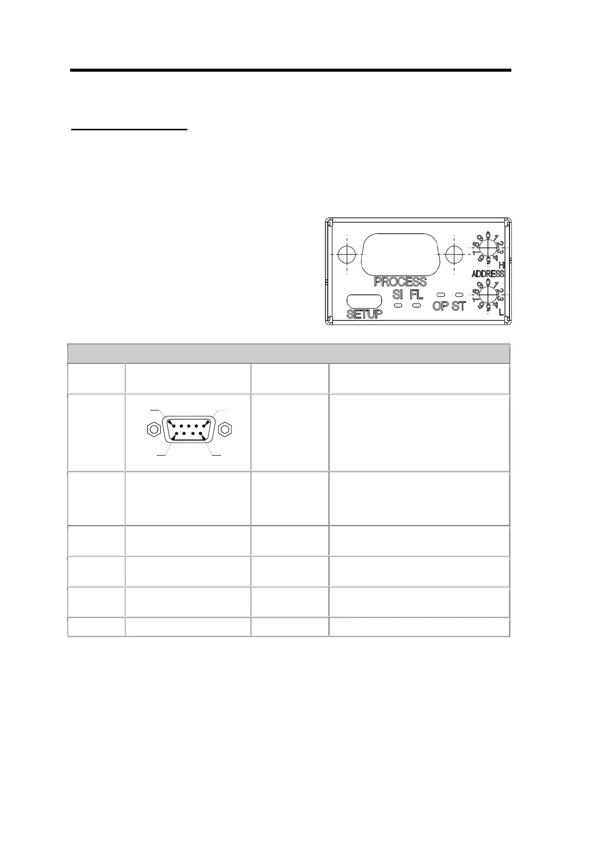
2W-Modbus Pinout
Pin IDv Signal EIA/TIA 485
Name
Description
PIN 5
PIN 9
PIN 1
PIN 6
Sub D 9-poles,
socket
3 PMC -- Port Mode Control
Open Æ 2W-Mode
Low level (connected with Common)
Æ 4W-Mode
5 D1 B/B’ Transceiver terminal 1, V1 Voltage
(V1 > V0 for binary 1[OFF] state)
9 D0 A/A’ Transceiver terminal 0, V0 Voltage
(V0 > V1 for binary 0 [ON] state)
2 VP -- DC Power Supply
Positive 20 to 30 V
1 Common C/C’ Signal and Power Supply Common