Chapter 5: Process Interfaces
57
Operation
Address
If the software address setting is 126, the address is set via the rotary switches (up to address 99).
Otherwise the rotary switch setting is irrelevant and the software address setting is used.
Configuration (GSD)
For the configuration of the MFC with a PC a GSD file is required. You will find the file on the CD,
which is part of the delivery. There are two GSD files. For the use with Profibus DPV 0 (order code
MF1_ _ _ _ _ _ _ _ 4 _ _) select “MKS_1179.gsd and for the Profibus DPV1 (order code MF1_ _
_ _ _ _ _ _ P _ _) select MKS_0C0B.gsd. The DPV 0 is compatible to the 1179B Profibus.
The Profibus DPV1 supports the acyclic communication.
Feedback and Diagnostics
Error codes
Error codes are defined by the Profibus specification.
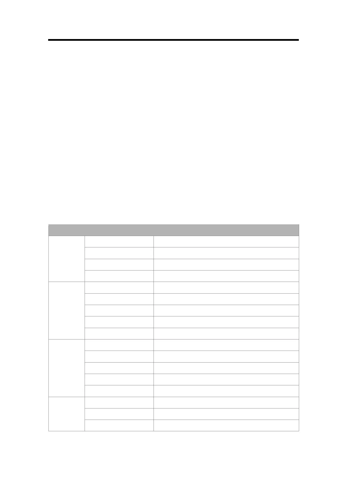
LED Functions
LED Signals
Off No power or not initialized
Green Initialized
Flashing green Initialized, diagnostic events present
ST
Red Exception error
Off No power, not initialized
Green Online, data exchange
Flashing green Online, clear
Flashing red (1 flash) Parametrization error
OP
Flashing red (2 flashes) PROFIBUS Configuration error
Green Sensor OK
Flashing red Power too low
Blue Pure USB operation
Flashing red & green Self Test or Boot
SI
Flashing blue Shows Seconds forAUTOZERP button
Off No flow
Flashing blue Flow Indicator: Flashes proportional to actual flow
FL
Blue on 100% Flow