Chapter 5: Process Interface
58
Protocol (PROFIBUS cyclic telegrams)
Data Interface
The MF1 with PROFIBUS have a small data interface with a basic function set and a full data
interface with the full function set of the device. The selection between small and full functionality is
made at setup time with the type of configuration data, which is loaded down, to the device.
• Small / Full Parameter selects the internal function set and is declared by the GSD file
parameters:
User_Prm_Data_Len and User_Prm_Data. The content of these parameters is either the
small setup or full setup structure.
• Small / Full Receive Data, is selected by the MODULE definition in the GSD file. E.g.:
Module = "SMALL_MFC" 0x91, 0xD5, 0xA1, 0xE1 or
Module = "FULL_MFC" 0x91, 0xD7, 0xA1, 0xE1
The data interfaces are documented as data structures with consecutive fields. There is a table
entry for each field, with name, address (add), type information and a comment for explanation.
The address field (Add.) defines the byte and bit address (ByteOffset:BitOffset). For the memory
layout the Motorola Format is used. The following types are used:
• uint:X an unsigned integer with X bits length.
• long signed long integer (4 bytes)
• uint16 unsigned integer (2 bytes, word)
• uint8 unsigned integer (byte)
• char[X] character array of length X
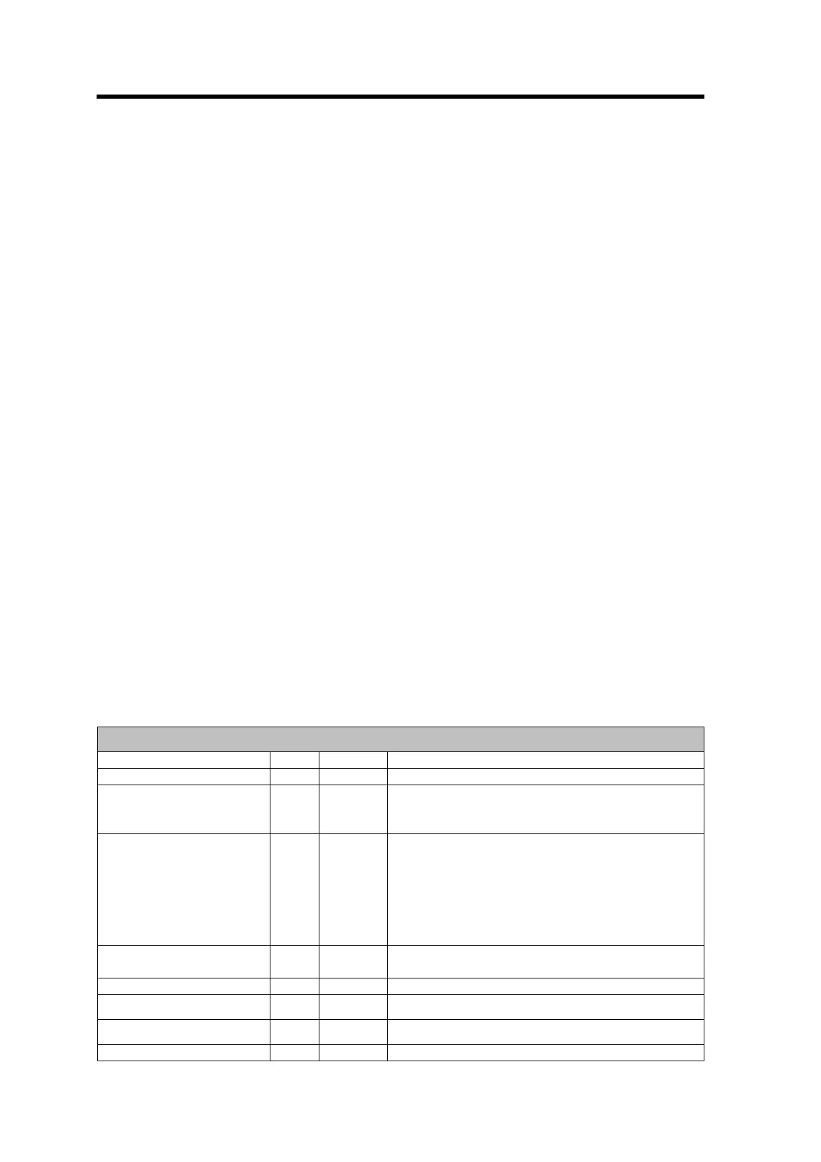
Send Data
Send data
Name Add. Type Comment
VALVE_OVERRIDE 1:0 uint:2 NORMAL, FLOW_OFF, PURGE
AUTOZERO 1:2 uint:1 0 to 1 transition activates zeroing if
(VALVE_OVERRIDE==FLOW_OFF &&
FLOW_SETPOINT < 5%FS)
REPORT_DIAG 1:3 uint:3 transition to a new value, triggers the device to
send a new actual diagnosis:
0 = no diagnosis
1 = diagnosis of small functionality
2 = diagnosis of full functionality
3 = report selected gas table
4..7 = reserved
WINK_STATUS 1:6 uint:1 0 to 1 transition sets the LED to blink red/green
for 3 seconds
ENABLE_TOTALIZER 1:7 uint:1 0 = disabled, 1 = enabled
RESET_TOTALIZER 0:0 uint:1 0 to 1 transition resets totalizer to zero
RESET_STATUS 0:1 uint:1 0 to 1 transition resets error status bits
SELECT_GAS_TABLE 0:2 uint:4 0..14; 15 = default gas table is used