Chapter 5: Process Interface
64
Analog Process Interface
Functions
Valve Override
The valve override feature enables the control valve to be fully opened (purged) or closed
independent of the set point command signal:
To close the valve, apply a TTL low to pin 1 or connect pin 1 to pin 7 (SIG_GND).
To open the valve, apply a +5 V signal to pin 1. This command may be used to purge or vent the
instrument or the system.
Scaling the Signal
The scaling of the MF1 analog output signal could be changed via the USB Setup interface. The
scaling range is 0 to 2 V for the zero signal (0%) and 5 to 10 V for the F.S. signal (100%), which
means an output signal 2 to 7 V or 0 to 10 V could be setup. Default setting is 0 to 5 V. The voltage
is proportional to the flow. The setpoint input is always scaled as the output signal. The resolution
of the voltage signal is 0.4 mV independent of the used scaling. For changing the scaling see
Chapter 4.
Installation
Pinout
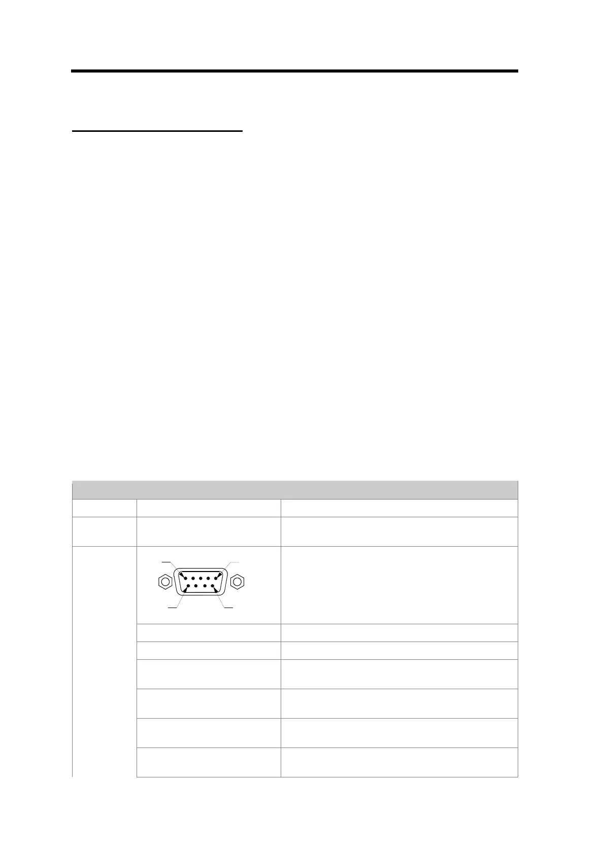
Analog Interface
Item Detail Description
SETUP - Mini USB connector, present for every interface
variant. Operates as MSD or CDC.
PIN 5
PIN 9
PIN 1
PIN 6
Standard D-Sub connector
Pin-1: VALVE_OVERRIDE Apply PWR_GND for close, apply +5V for open
Pin-2: FLOW Default Range 0..5V, reference to SIG_GND
Pin-3: [POWER+] +15V dual supply or 24V single supply (Surge
protected)
Pin-4: [POWER_GND] Power ground for dual supply, signal ground for
single supply
Pin-5: [POWER -] -15V or power ground for single supply; connected
to “–“ of the Phönix connector.
ANALOG
Pin-6: SETPOINT Set point input; default 0 – 5 V; reference to
SIG_GND