MOTOROLA M68020 USER’S MANUAL 8- 5
ACTIVIT
YTES n +
ONTROLLE
BYTES n + 12
MOVE #1
ADD #2
OURCE E
MOVE #3
ESTINATIO
EA
MOVE #3
MOVE #3
ADD #4
D5,D
XECUTION TIM
OUN
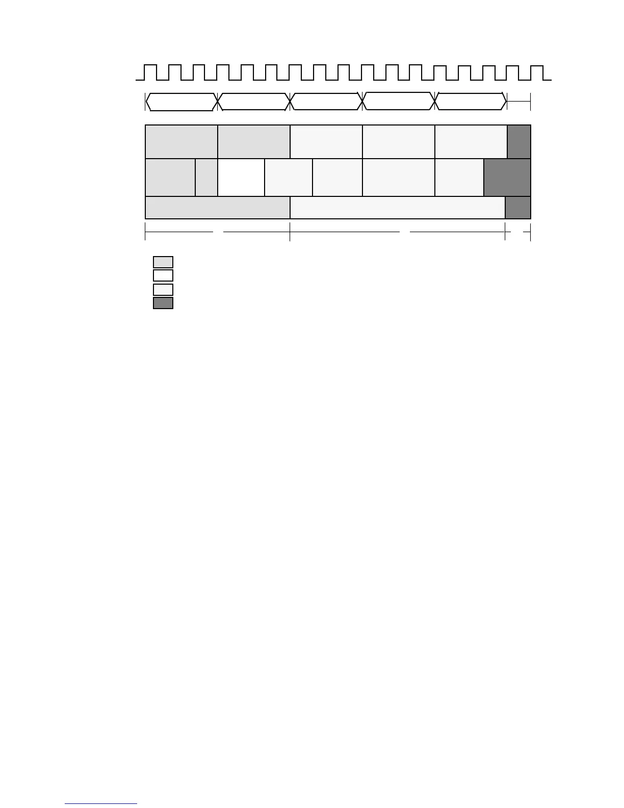
Figure 8-3. Processor Activity for Example 1
For the first three clocks of this example, the bus controller and sequencer are both
performing tasks associated with the MOVE #1 instruction. The next three clocks (clocks
4, 5, and 6) demonstrate instruction overlap. The bus controller is performing a write to
memory as part of the MOVE #1 instruction. The sequencer, on the other hand, is
performing the ADD #2 instruction for two clocks (clocks 4 and 5) and beginning source
effective address (EA) calculations for the MOVE #3 instruction. The bus controller activity
completely overlaps the execution of the ADD #2 instruction, causing the ADD #2
attributed execution time to be zero clocks. The overlap also shortens the effective
execution time of the MOVE #3 instruction by one clock because the bus controller
completes the MOVE #1 write operation while the sequencer begins the MOVE #3 EA
calculation.
The sequencer continues the source EA calculation for one more clock period (clock 7)
while the bus controller begins a read for MOVE #3. When counting instruction execution
time in bus clocks, the MOVE #1 completes at the end of clock 6, and the execution of
MOVE #3 begins on clock 7.
Both the sequencer and bus controller continue with MOVE #3 until the end of clock 14,
when the sequencer begins to perform ADD #4. Timing for MOVE #3 continues because
the bus controller is still performing the write to the destination of MOVE #3. The bus
activity for MOVE #3 completes at the end of clock 15. The effective execution time for
MOVE #3 is nine clocks.
The one clock cycle (clock 15) when the sequencer is performing ADD #4 and the bus
controller is writing to the destination of MOVE #3 is absorbed by the execution time of
MOVE #3. This overlap shortens the effective execution time of ADD #4 by one clock,
giving it an attributed execution time of one clock.

 Loading...
