MOTOROLA M68020 USER’S MANUAL 7- 5
To improve the efficiency of operand transfers between memory and the coprocessor, a
coprocessor that requires a relatively high amount of bus bandwidth or has special bus
requirements can be implemented as a DMA coprocessor. The DMA coprocessor
provides all control, address, and data signals necessary to request and obtain the bus
and then performs DMA transfers using the bus. DMA coprocessors, however, must still
act as bus slaves when they require information or services of the main processor using
the M68000 coprocessor interface protocol.
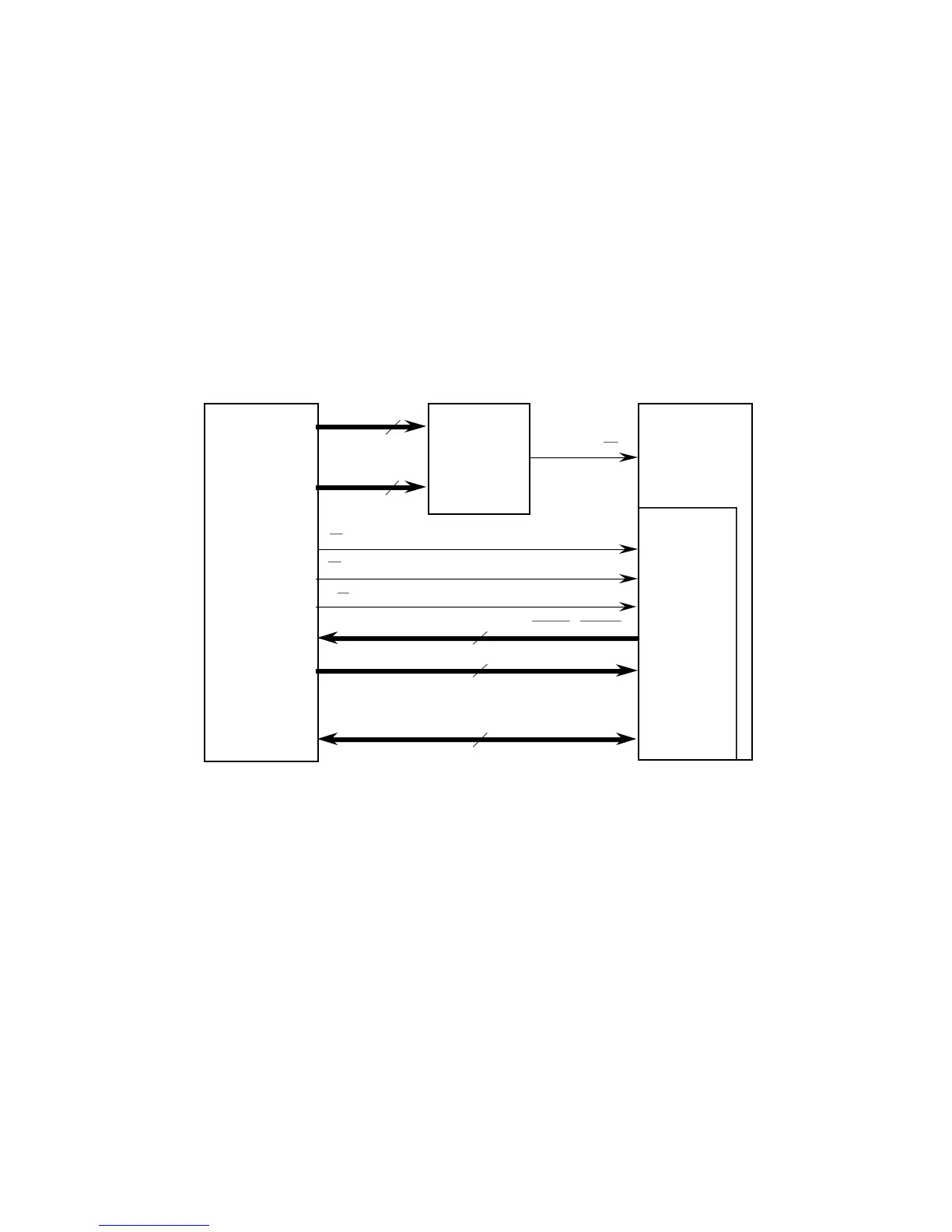
7.1.4.2 PROCESSOR-COPROCESSOR INTERFACE. Figure 7-2 is a block diagram of
the signals involved in an asynchronous non-DMA M68000 coprocessor interface. Since
the CpID on signals A15–A13 of the address bus is used with other address signals to
select the coprocessor, the system designer can use several coprocessors of the same
type and assign a unique CpID to each one.
DECODE
LOGIC
BUS
INTERFACE
LOGIC
MC68020/EC020
19–A16 = 0010
15–A13 = xxx
4–A1 = rrrr
*Chip select logic may be integrated into the coprocessor.
Address lines not specified above are "0" during coprocessor access.
➧
➧
➧
➧
OPROCESSOR ACCESS IN CPU SPACE
OPROCESSOR IDENTIFICATION
OPROCESSOR INFERFACE REGISTER SELECTOR
Figure 7-2. Asynchronous Non-DMA M68000
Coprocessor Interface Signal Usage
The MC68020/EC020 accesses the registers in the CIR set using standard asynchronous
bus cycles. Thus, the bus interface implemented by a coprocessor for its interface register
set must satisfy the MC68020/EC020 address, data, and control signal timing. The
MC68020/EC020 bus operation is described in detail in Section 5 Bus Operation.

 Loading...
