8- 8 M68020 USER’S MANUAL MOTOROLA
ACTIVIT
ONTROLLE
MOVE #1
ADD #2
OURCE E
MOVE #3
MOVE #3
XECUTION TIM
COUNTE
ADD #4
ESTINATIO
EA
MOVE #3
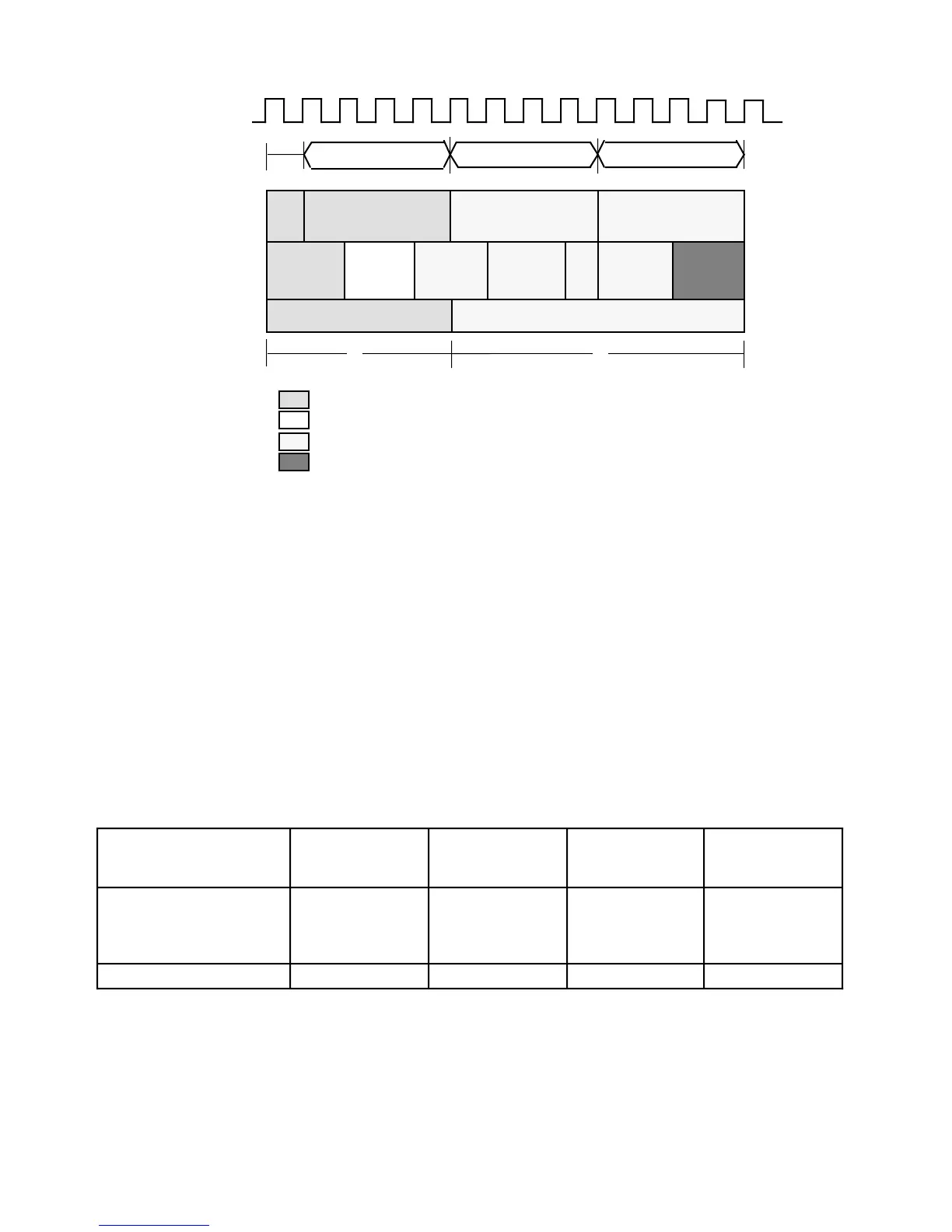
Figure 8-6. Processor Activity for Example 4
Figure 8-6 shows the same instruction stream executing with four clocks for every read
and write. The idle bus cycles coincide with the wait states of the memory access;
therefore, the total execution time is only 13 clocks.
Examples 1–4 demonstrate the complexity of instruction timing calculation for the
MC68020/EC020. It is impossible to anticipate individual instruction timing as an absolute
number of clock cycles due to the dependency of overlap on the instruction sequence and
alignment as well as the number of wait states in memory. This can be seen by comparing
individual and composite time for Figures 8-3 through 8-6. These instruction timings are
compared in Table 8-1, where timing varies for each instruction as the context varies.
Table 8-1. Examples 1–4 Instruction Stream Execution Comparison
Instruction
Example 1
(Odd Alignment)
Example 2
(Even Alignment)
Example 3
(Cache)
Example 4
(Cache with
Wait States)
#1) MOVE.L
#2) ADD.L
#3) MOVE.L
#4) ADD.L
D4,(A1)+
D4,D5
(A1),–(A2)
D5,D6
6
0
9
1
4
3
6
3
4
0
7
1
5
0
8
0
Total Clock Cycles 16 16 12 13

 Loading...
