5- 8 M68020 USER’S MANUAL MOTOROLA
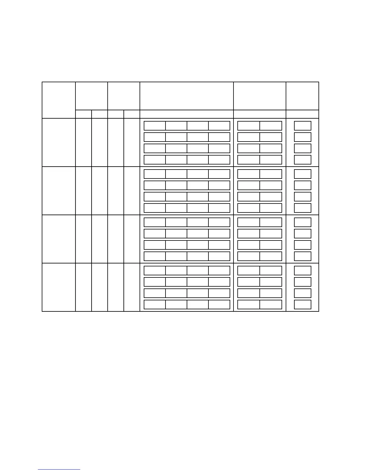
Table 5-4 lists the bytes required on the data bus for read cycles. The entries shown as
OP3, OP2, OP1, and OP0 are portions of the requested operand that are read or written
during that bus cycle and are defined by SIZ1, SIZ0, A1, and A0 for the bus cycle.
Table 5-4. Data Bus Requirements for Read Cycles
Byte Port
External
Data Bytes
Required
Word Port
External Data Bytes
Required
Long-Word Port
External Data Bytes
Required
AddressSize
Transfer
Size
SIZ1 SIZ0 A1 A0
OP3 OP3
OP3
OP3
OP3 OP3
OP3
OP3
OP3
D31–D24D23–D16D31–D24D23–D16D31–D24 D7–D0D15–D8
OP3
OP3
OP3
Byte 0
1
1
1
100
0
0
0
1
1
01
0
1
OP2 OP2
OP2
OP2
OP2 OP2
OP2
OP2
OP2
OP2
OP2
OP2
Word 1
0
1
1
000
1
1
1
0
0
01
0
1
OP1 OP1
OP1
OP1
OP1 OP1
OP1
OP1
OP1
OP1
OP1
OP1
3 Bytes 1
1
1
1
100
1
1
1
1
1
01
0
1
OP0 OP0
OP0
OP0
OP0 OP0
OP0
OP0
OP0
OP0
OP0
OP0
Long Word 0
0
1
1
000
0
0
0
0
0
01
0
1
OP3
OP3
OP2
OP2
OP1
OP1
OP1
OP1
OP2
OP1
OP2
OP3
OP2
OP3OP2
OP3OP2
OP3
OP3
OP3

 Loading...
