MOTOROLA M68020 USER’S MANUAL 3- 1
SECTION 3
SIGNAL DESCRIPTION
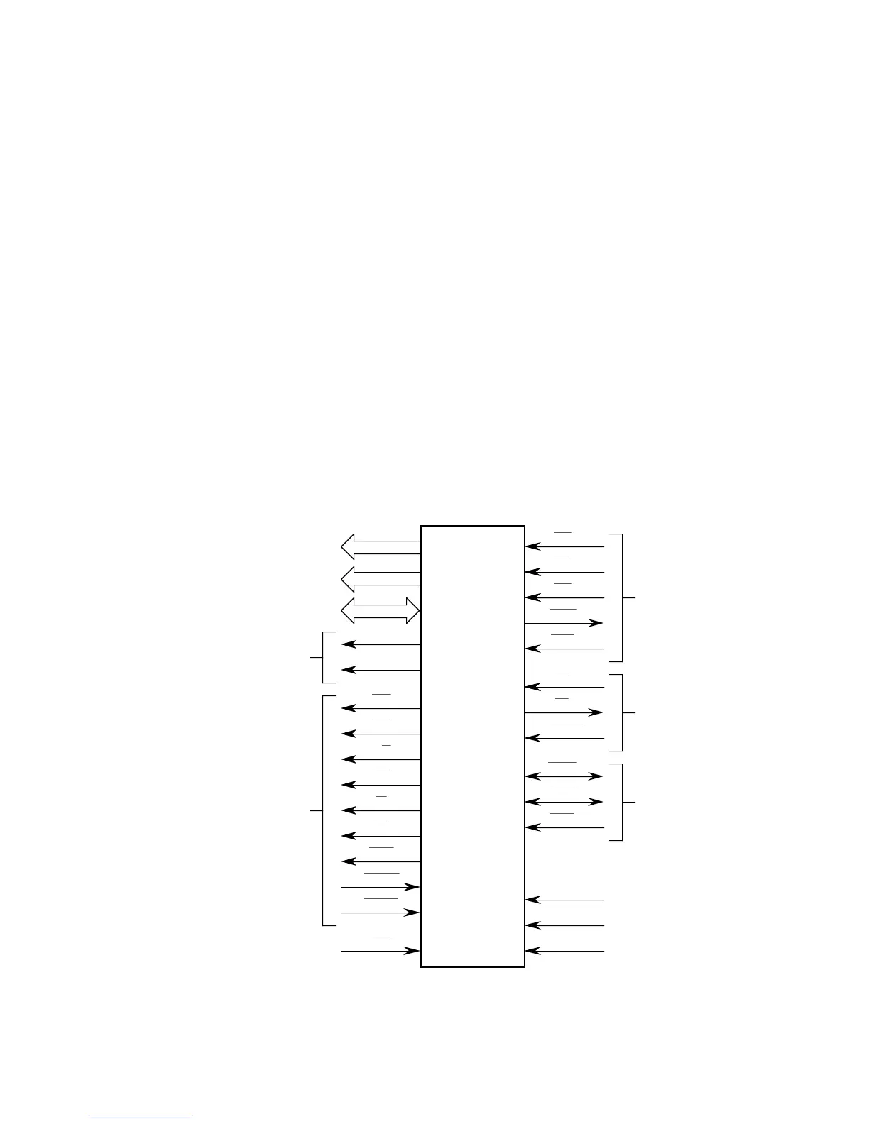
This section contains brief descriptions of the input and output signals in their functional
groups, as shown in Figure 3-1. Each signal is explained in a brief paragraph with
reference to other sections that contain more detail about the signal and the related
operations.
NOTE
In this section and in the remainder of the manual,
assert
and
negate
are used to specify forcing a signal to a particular state.
In particular,
assertion
and
assert
refer to a signal that is active
or true;
negation
and
negate
indicate a signal that is inactive or
false. These terms are used independently of the voltage level
(high or low) that they represent.
C2–FC
31–A
31–D
FUNCTION CODE
ADDRESS BU
ATA BU
RANSFER SIZ
ASYNCHRONOU
BUS CONTRO
EMULATOR SUPPOR
US A
ONT
NTER
ONT
US E
ONT
MC68020
IZ
IZ
C
C
/W
M
BE
SACK
SACK
DI
N
L
ER
AL
ESE
GAC
VE
PEN
PL
PL
PL
*
*
*
**
*
*
Figure 3-1. Functional Signal Groups

 Loading...
