MOTOROLA M68020 USER’S MANUAL 5- 9
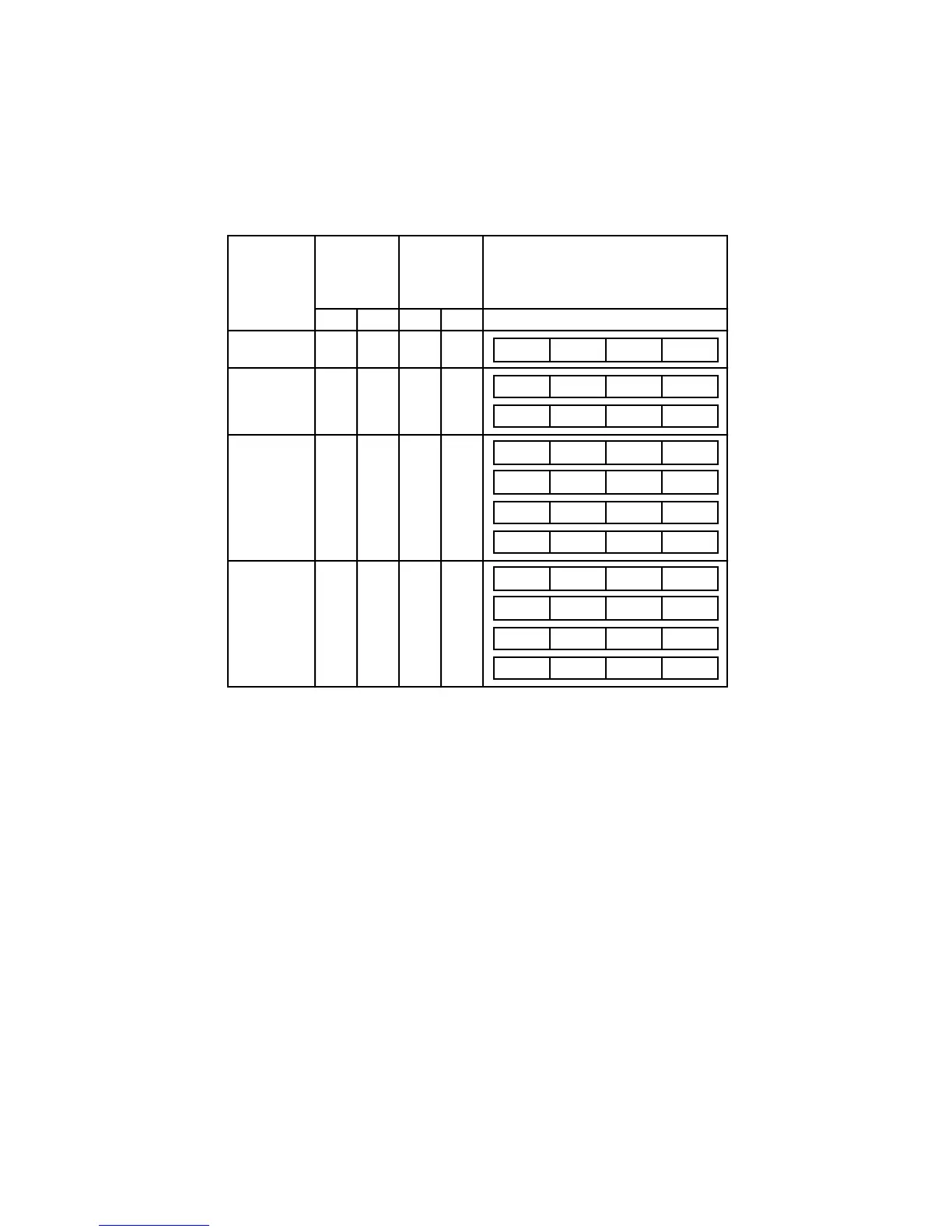
Table 5-5 lists the combinations of SIZ1, SIZ0, A1, and A0 and the corresponding pattern
of the data transfer for write cycles from the internal multiplexer of the MC68020/EC020 to
the external data bus.
Table 5-5. MC68020/EC020 Internal to External Data Bus
Multiplexer—Write Cycles
OP0*
External Data Bus
Connection
AddressSize
Transfer
Size
SIZ1 SIZ0 A1 A0
OP3
D23–D16
D31–D24
D7–D0D15–D8
Byte 0 1 x x
OP2
OP2
Word 1
0
0
x0
1
x1
OP1
OP1
OP1
OP1
3 Bytes 1
1
1
1
100
1
1
1
1
1
01
0
1
OP0
OP0
OP0
OP0
Long Word 0
0
1
1
000
0
0
0
0
0
01
0
1
OP1
OP1
OP2
OP1
OP2
OP3
OP2
OP3OP2
OP3OP2
OP3
OP3
OP3
OP2
OP3
OP2
OP3
OP3
OP1
OP1
OP1
OP2
OP1
OP0
OP0
OP0
OP1
OP0 OP1*
OP2
OP2*
*Due to the current implementation, this byte is output but never used.
x = Don't care
NOTE: The OP tables on the external data bus refer to a particular byte of the operand that
is written on that section of the data bus.

 Loading...
