6 Wiring of the Device
Rev. 03/2019 45
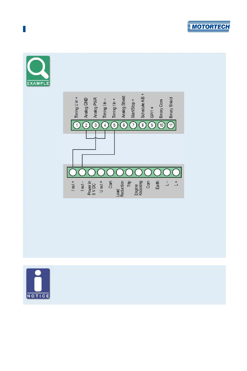
Wiring MIC5 ignition controller and DetCon detonation control system
The following diagram shows an example of the wiring of a MIC5 ignition
controller with a DetCon detonation control system in cases where the
analog current signal (4-20 mA) at the output I out is to be used for the
ignition timing adjustment.
MIC5
ignition
controller
DetCon
detonation
control system
Furthermore, the limits of the analog current input will need to be set at
4 mA to 20 mA and the auxiliary supply voltage of the analog inputs to 24 V
in the MICT. Please refer to the section Timing – Analog Inputs on page 100.
The timing is transmitted by MIC5 via the auxiliary synchronization output
(ASO) to the DetCon, and will need to be wired and configured accordingly.
Please refer to the section Output Wiring – Binary Outputs (Go/NoGo, GPO,
ASO) on page 46.
General purpose input GPI
The general purpose input GPI can be assigned various functions via the
configuration. Refer to the section Inputs/Outputs – Inputs on page 110.