7 Functions and settings
Maschinenfabrik Reinhausen 2014112 222/08 ENTAPCON® 240
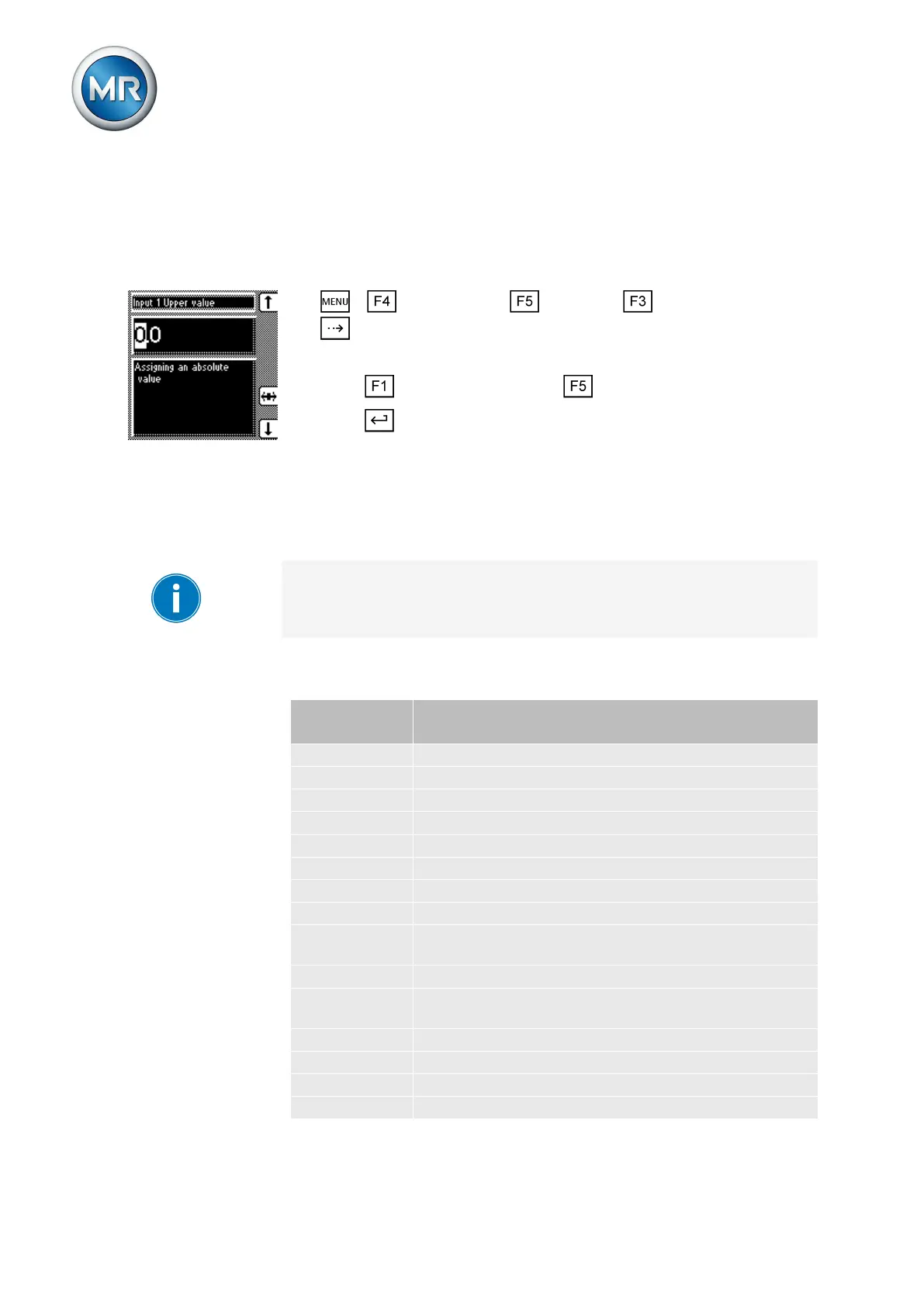
Setting upper value of input signal
To configure the analog input, an absolute value must be assigned to the up-
per value of the applied signal.
To set the upper value for the input, proceed as follows:
1. > Configuration > Continue > Analog inputs > Press
until the desired parameter is displayed.
ð Input 1 upper value.
2. Press to increase the value or to reduce it.
3. Press .
LED selection
You can use this parameter to assign functions to the 4 free LEDs [► 20]
which light up when an event occurs. You can use labeling strips to label
them.
Depending on your device configuration, the following parameters can be
used by MR for special functions. In this case, these parameters are pre-as-
signed. You may not be able to view or freely assign these parameters.
An overview of all possible functions which you can assign to the LEDs is
provided in the table below.
Functions
available
Function description
Off LED deactivated
IOxx/UCxx There is a signal at control input IOxx/UCxx (e.g. IO:25)
SI:bef1 SI:bef1 (command) is received
SI:bef2 SI:bef2 (command) is received
Undervoltage Undervoltage present
Overvoltage Overvoltage present
Overcurrent Overcurrent present
Par. error Parallel operation error present
Motor protec-
tion
Motor protective switch triggered
Blocking Regulation is blocked
Circulating re-
active current
Parallel operation selected using circulating reactive
current method
Master Device in parallel operation activated as master
Follower Device in parallel operation activated as follower
Automatic Auto mode activated
Bandwidth < Value is below bandwidth
7.11
Functions available for
LEDs