7 Functions and settings
Maschinenfabrik Reinhausen 201470 222/08 ENTAPCON® 240
Visual display
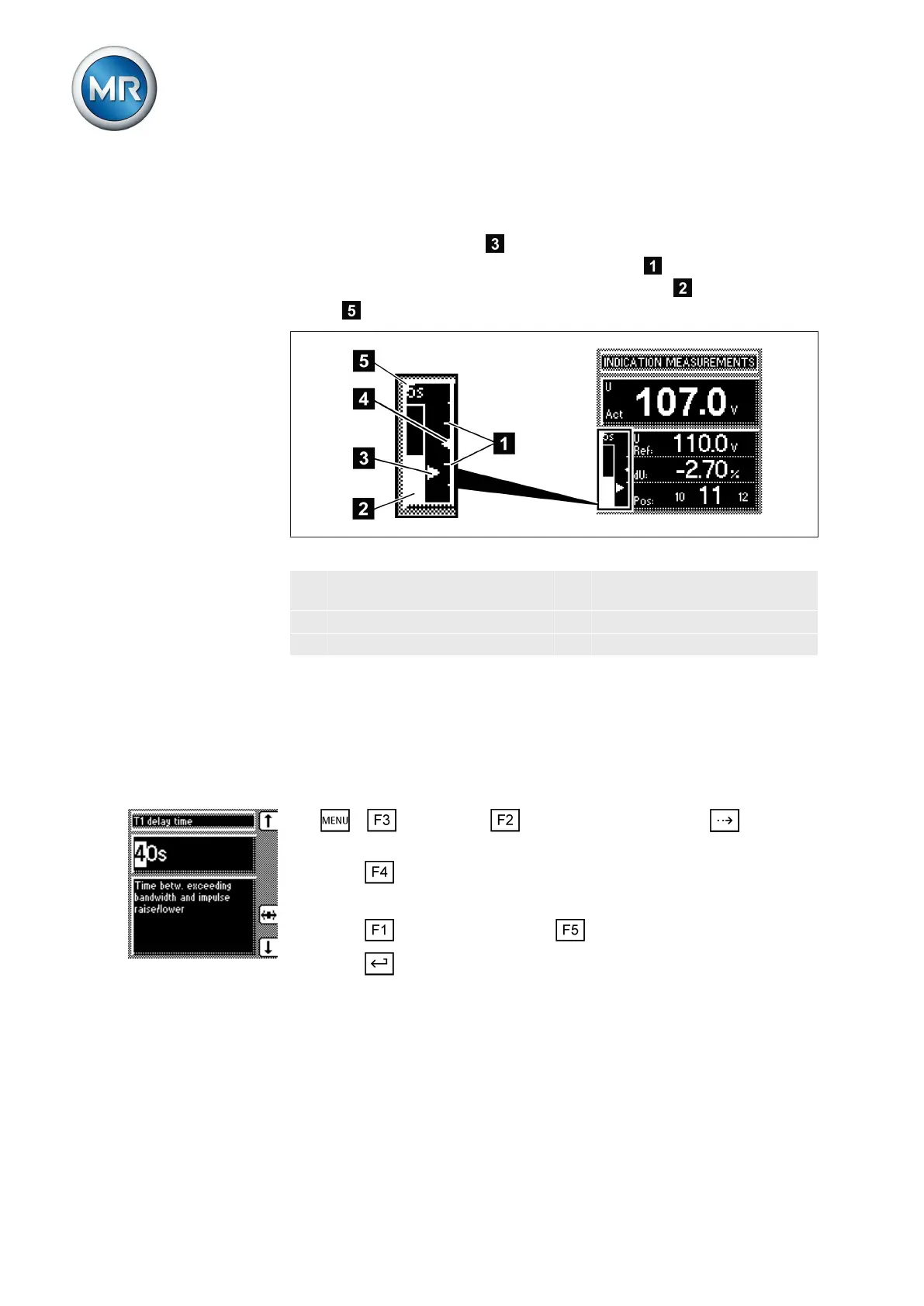
The deviation from the set bandwidth is shown visually in the device's dis-
play. The measured voltage highlighting shows whether the measured
voltage is above, within or below the set bandwidth . Progress of delay
time T1 is indicated by the gradual filling of the time bar
. The seconds
display above this indicates the remaining delay time T1.
Figure 43: Visual display of deviation from desired value
1 Bandwidth (upper and lower
limit)
4 Desired voltage value U
Ref
2 Time bar for delay time T1 5 Remaining delay time T1
3 Measured voltage U
Act
Setting delay time T1
Use this parameter to set delay time T1. This function delays the issuing of a
tap-change command for a defined period. This prevents unnecessary tap-
change operations if the tolerance bandwidth is exited.
To set the delay time T1, proceed as follows:
1. > Parameter > Control parameter > Press until the
desired parameter is displayed.
2. Press to highlight the position.
ð The desired position is highlighted and the value can be changed.
3. Press to increase the time or to reduce it.
4. Press .
ð The delay time T1 is set.
Setting control response T1
The control response T1 can be set to linear or integral.
With linear control response, the device responds with a constant delay time
regardless of the control deviation.
7.4.2.3
7.4.3
7.4.4
Linear control response T1