7 Functions and settings
Maschinenfabrik Reinhausen 2014104 222/08 ENTAPCON® 240
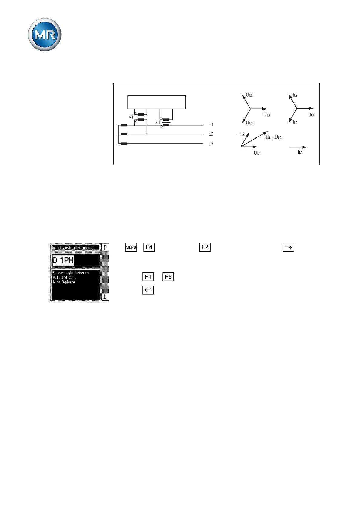
Circuit F
Figure 64: Phase difference -30 3PH
▪ The voltage transformer VT is connected to the outer conductors L1 and
L2.
▪ The current transformer CT is looped into the outer conductor L1.
▪ The current I
L1
lags behind U
L1
-U
L2
by 30°. This corresponds to a phase
shift of -30°.
▪ The voltage drop on an outer conductor is determined by the current I
L1
.
To set the phase difference for the transformer circuit, proceed as follows:
1. > Configuration > Transformer data > Press until the
desired parameter is displayed.
ð Transformer circuit.
2. Press or to select the required phase difference.
3. Press .
ð The phase difference is set.
Parallel operation
In theParallel operation menu item, you can set the parameters needed for
parallel transformer operation. Parallel transformer operation is used to in-
crease the throughput capacity or short-circuit capacity in one place.
Compliance with the following general conditions is required for operating
transformers in parallel:
▪ Identical rated voltages
▪ Transformer power ratio (< 3 : 1)
▪ Maximum deviation of short-circuit voltages (U
K
) for transformers con-
nected in parallel < 10%
▪ Same number of switching groups
▪ The same current-transformer connection has to be used for all devices
running in parallel
7.9
Conditions for parallel
operation