13 Technical data
Maschinenfabrik Reinhausen 2014 161222/08 EN TAPCON® 240
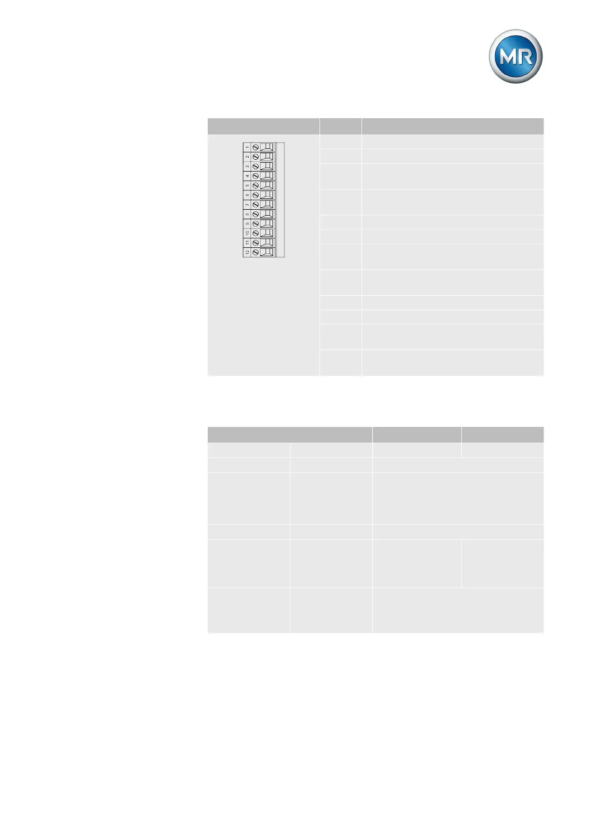
Interface Pin Description
1 Voltage transformer L1
2 Voltage transformer L1
3 Return conductor of current transform-
er L1
4 Current transformer L1 (rated current 5
A)
5 Voltage transformer L2
6 Voltage transformer L2
7 Return conductor of current transform-
er L2
8 Current transformer L2 (rated current 5
A)
9 Voltage transformer L3
10 Voltage transformer L3
11 Return conductor of current transform-
er L3
12 Current transformer L3 (rated current 5
A)
Table 52: MI3-G card terminal X1
Digital inputs and outputs
IO UC
Inputs Quantity 9 10
Logical 0 0...25 V DC
Logical 1 40...250 V DC
With pulsating DC voltage, the volt-
age minimum must always exceed
40 V.
Input current Min. 1 mA
Outputs Number (num-
ber of change-
over contacts in
parentheses)
8 (5) 10
Contact loada-
bility
Min.: 12 V, 100 mA
Max. AC: 250 V, 5 A
Max. DC: See diagram
Table 53: Digital inputs and outputs
13.4