7 Functions and settings
Maschinenfabrik Reinhausen 2014 103222/08 EN TAPCON® 240
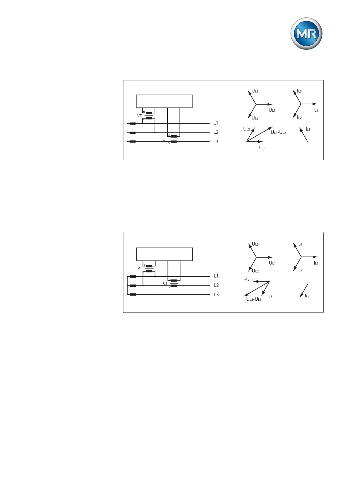
Circuit D
Figure 62: Phase difference 90 3PH
▪ The voltage transformer VT is connected to the outer conductors L1 and
L2.
▪ The current transformer CT is looped into the outer conductor L3.
▪ The current I
L3
is ahead of voltage U
L1
-V
L2
by 90°.
▪ The voltage drop on an outer conductor is determined by the current I
L3
.
Circuit E
Figure 63: Phase difference 30 3PH
▪ The voltage transformer VT is connected to the outer conductors L1 and
L2.
▪ The current transformer CT is looped into the outer conductor L2.
▪ The current I
L2
is ahead of voltage U
L2
-U
L1
by 30°.
▪ The voltage drop on an outer conductor is determined by the current I
L2
.