7 Functions and settings
Maschinenfabrik Reinhausen 2014102 222/08 ENTAPCON® 240
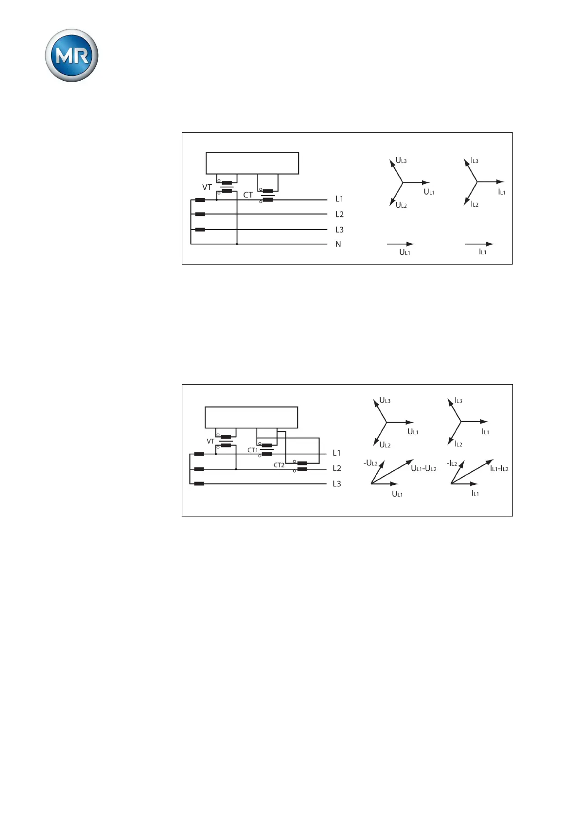
Circuit B: 1-phase measurement in 3-phase grid
Figure 60: Phase difference 0 3PHN
▪ The voltage transformer VT is connected to the outer conductors L1 and
neutral.
▪ The current transformer CT is looped into the outer conductor L1.
▪ The voltage U and current I are in phase.
▪ The voltage drop on an outer conductor is determined by the current I
L1
.
Circuit C:
Figure 61: Phase difference 0 3PH
▪ The voltage transformer VT is connected to the outer conductors L1 and
L2.
▪ The current transformer CT1 is looped into the outer conductor L1 and
CT2 into the outer conductor L2.
▪ The current transformers CT1 and CT2 are connected crosswise in par-
allel (total current = I
L1
+ I
L2
).
▪ The total current I
L1
+ I
L2
and voltage U
L1
-U
L2
are in phase.
▪ The voltage drop on an outer conductor is determined by the current:
(I
L1
+ I
L2
) / √3.