7 Functions and settings
Maschinenfabrik Reinhausen 2014142 222/08 ENTAPCON® 240
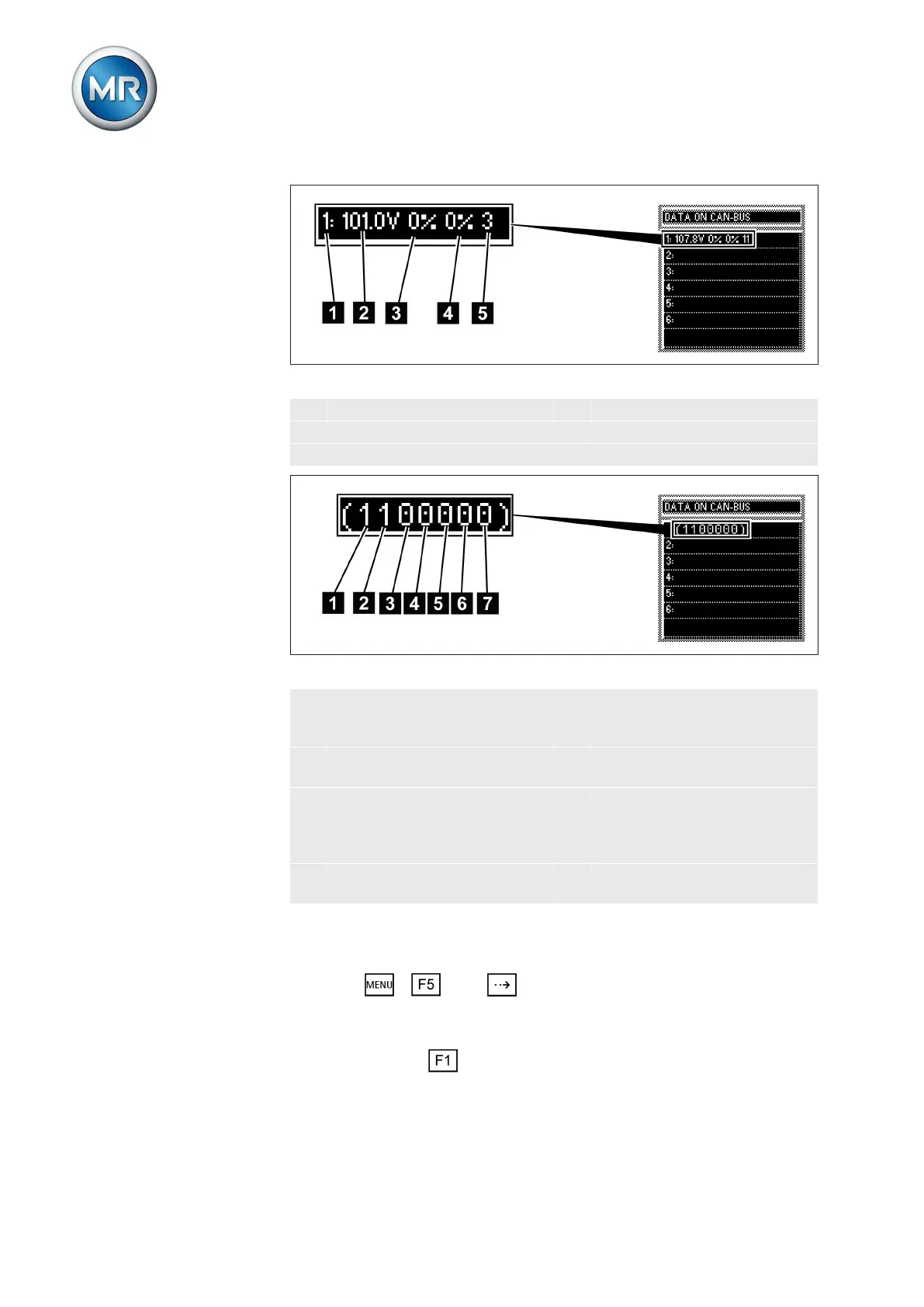
Figure 104: CAN bus data
1 CAN bus address of device 4 Reactive current in %
2 Voltage in V 5 Current tap position
3 Active current in %
Figure 105: Other CAN bus data
1 Group input 1 5 Follower tap synchronization
(0 = deactivated; 1 = activat-
ed)
2 Group input 2 6 Auto tap synchronization (0 =
deactivated; 1 = activated)
3 Circulating reactive current
parallel operation (0 = deacti-
vated; 1 = activated)
7 Device blocks group because
parallel operation is experi-
encing a fault (0 = is not
blocked; 1 = is blocked)
4 Master tap synchronization (0
= deactivated; 1 = activated)
To display the CAN bus data, proceed as follows:
1. Press > Info > until the desired measurement parameter
is displayed.
ð DATA ON CAN BUS.
2. Press and hold to display more data.
ð The additional information is displayed until you release the key.