5 Mounting
Maschinenfabrik Reinhausen 2014 37222/08 EN TAPCON® 240
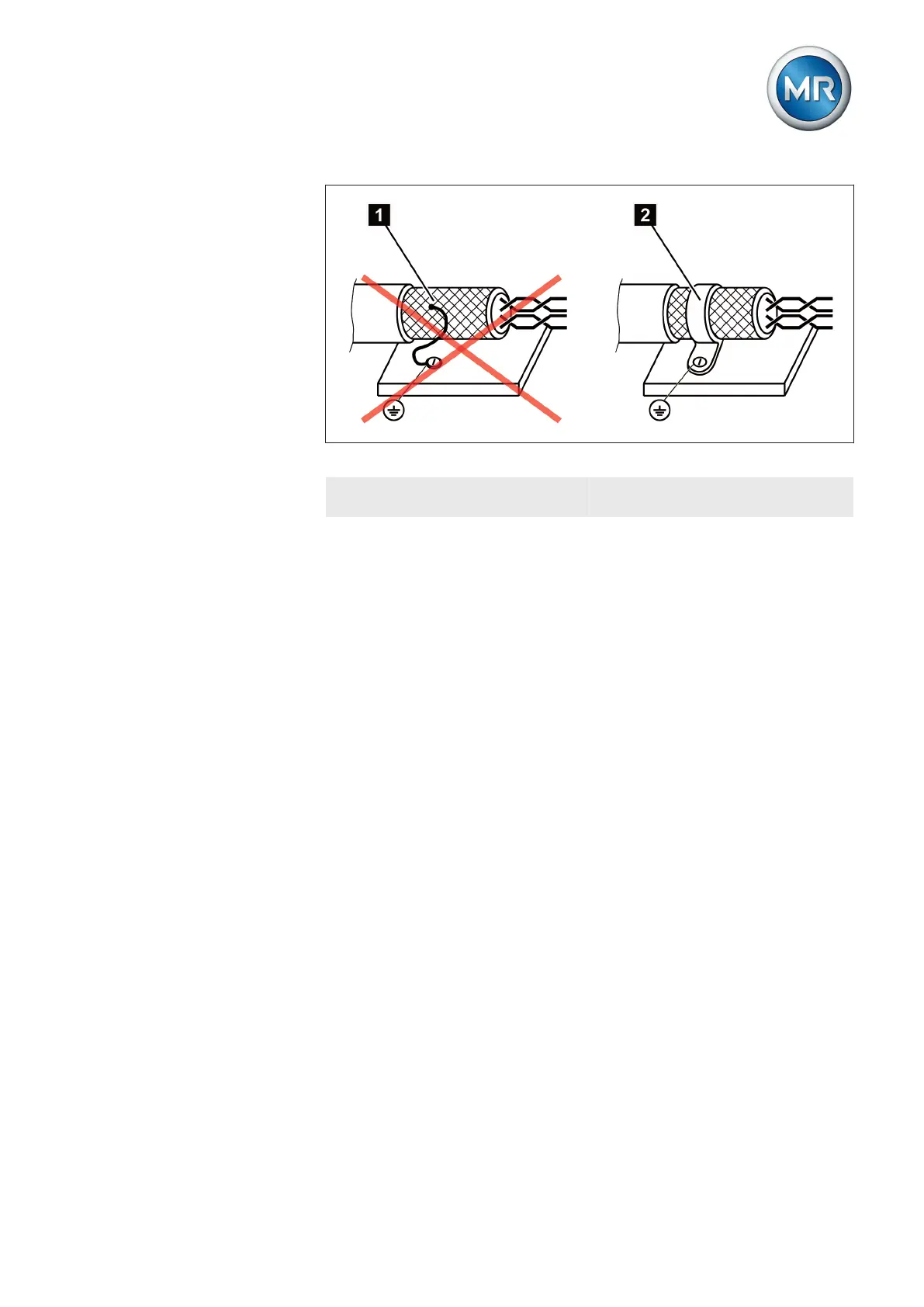
Figure 23: Recommended connection of the shielding
1 Connection of the shielding
using a "pigtail"
2 Shielding connection covering
all areas
Wiring requirement in control cabinet
Note the following when wiring the control cabinet:
▪ The control cabinet where the device will be installed must be prepared
in accordance with EMC requirements:
– Functional division of control cabinet (physical separation)
– Constant potential equalization (all metal parts are joined)
– Line routing in accordance with EMC requirements (separation of
lines which cause interference and those susceptible to interfer-
ence)
– Optimum shielding (metal housing)
– Overvoltage protection (lightning protection)
– Collective grounding (main grounding rail)
– Cable bushings in accordance with EMC requirements
– Any contactor coils present must be interconnected
▪ The device's connection cables must be laid in close contact with the
grounded metal housing or in metallic cable ducts with a ground con-
nection.
▪ Signal lines and power lines/switching lines must be laid in separate ca-
ble ducts.
▪ The device must be grounded at the screw provided, the protective
grounding connection, using a ground strap (cross-section min. 8 mm²).
5.3.3.3