Electrical system
- 39 -
E
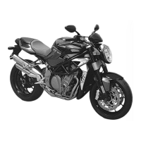
Consult the diagram below to identify the contacts of
the various components:
1 Supply
2 Gnd
3 + CAN
4 - CAN
5
6 High beam
7 Fuel warning led
8 Hazard out
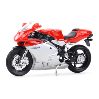
OIL PRESSURE SENSOR
To check the good functioning of this component with
the engine switched off, it is necessary to find the con-
tinuity between the contact of the sensor and the earth
of the motorcycle as shown in the figure.
With the engine switched on, the contact must be inter-
rupted.
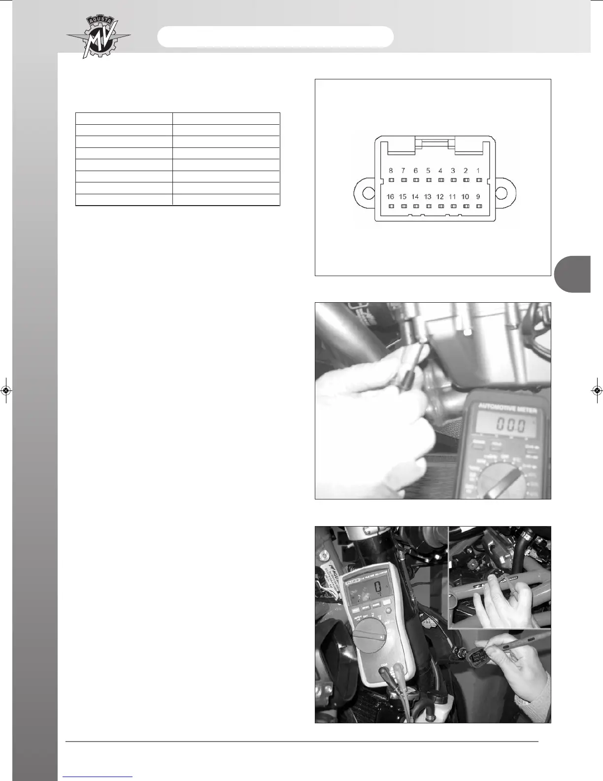
FUEL LEVEL WARNING LIGHT CHECK SWITCH
After having checked the breakdown of the fuel reser-
ve warning light, check that there is continuity between
terminal 4 of the tank flange and terminal 7 of the dash-
board.
9 ID warning led
10 Oil pressure
11 Ignition key
12 Serial Tx
13 Serial Rx
14 Immobilizer
15 Immobilizer
16
16 pin AMP 174975-2
 Loading...