- 16 -
Maintenance
B
Maintenance
VALVE MECHANISM ADJUSTMENT
Check and
adjust g Every 12000 kilometres
Remove in order the following components to carry out
the measuring of the play between the camshaft and the
valve cups:
• Left side fairing panel • LH fuel tank side panel
• Right side fairing panel • RH fuel tank side panel
• Under-engine fairing • Rear side panels
• Front fairing • Fuel tank
• Right air intake conduit cover • LH airbox side panel
• Left air intake conduit cover • RH airbox side panel
• Left air intake conduit • Air box
• Right air intake conduit • Throttle body
NOTE: For all removal operations, including the rela-
tive attention notes, please refer to the specific sec-
tions in this manual.
An analogous reference is utilised for the reassembly
of the parts after the maintenance operation.
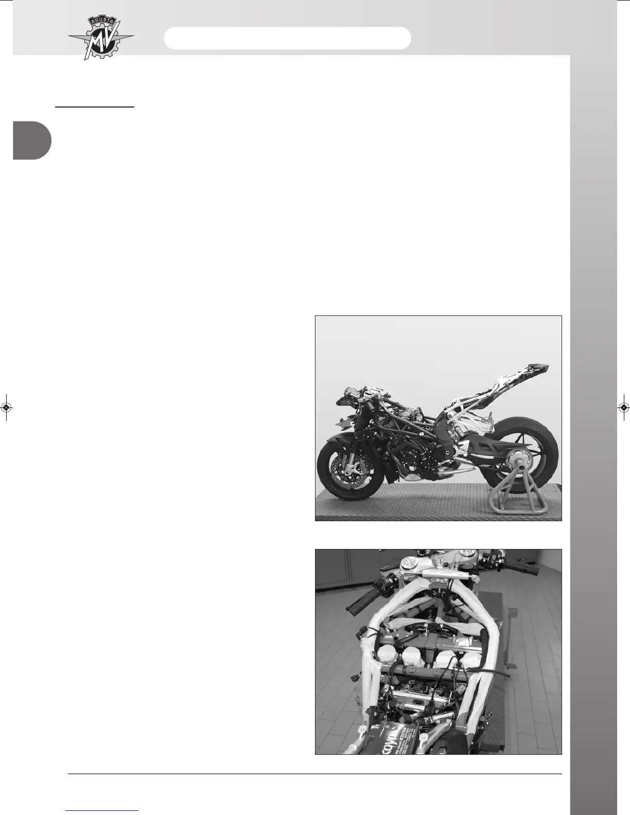
After having removed the indicated components, the
motorcycle is shown in the condition described by the
photograph on side.
Before proceeding with the various maintenance oper-
ations, it is advisable to thoroughly wash and clean the
motorcycle.
Place the motorcycle (now without the components
listed above and clean) on a workstation as indicated
in the figure.
Apply adhesive paper tape to the frame tubes.
This operation will protect the paintwork from knocks,
scratches and abrasions that could occur during the
work activity.
Ensure that all the surfaces of the frame are protected
by the application of the adhesive tape.
Apply the same adhesive tape to the air intakes of the
engine.