Electrical system
- 41 -
E
TURN INDICATORS
If the blinker warning lights do not work, continuity
must be checked on the cable R-B between terminal 7
of the switch connector and terminal 9 of the dash-
board connector.
Check the continuity between G (green) and Bk/W
(black/white) wires for the left blinker, and between G
(green) and Y/W (yellow/white) wires for the right blinker.
R.P.M. SENSOR (MY10 -> MY12)
Engine rev information on the dashboard arrives by
means of a CAN line; therefore, if this information is not
displayed and the message CAN ERROR appears on
the dashboard, the problem can be attributed to the
dashboard.
STARTER RELAY ACTIVATION
•
With the engine cut-off switch in the RUN position, press
and hold down the starter button and check if 12V is sup-
plied between relay switch wires B/Y and O/Y.
• If that is not the case, check if voltage is present
between the B/Y wire and ground
• If there is no voltage input , check the condition of
fuse E5 after which check the right hand control as
follows:
1) Disconnect the connector of the right hand con-
trol.
2) With the engine cut-off switch in the RUN posi-
tion, check for continuity between pins (2) and (5),
and then check for continuity between contacts (1)
and (3) while pressing the starter button.
3) If the right-hand control is in good working order,
the problem is due to a malfunction in the engine
control unit and its connections.
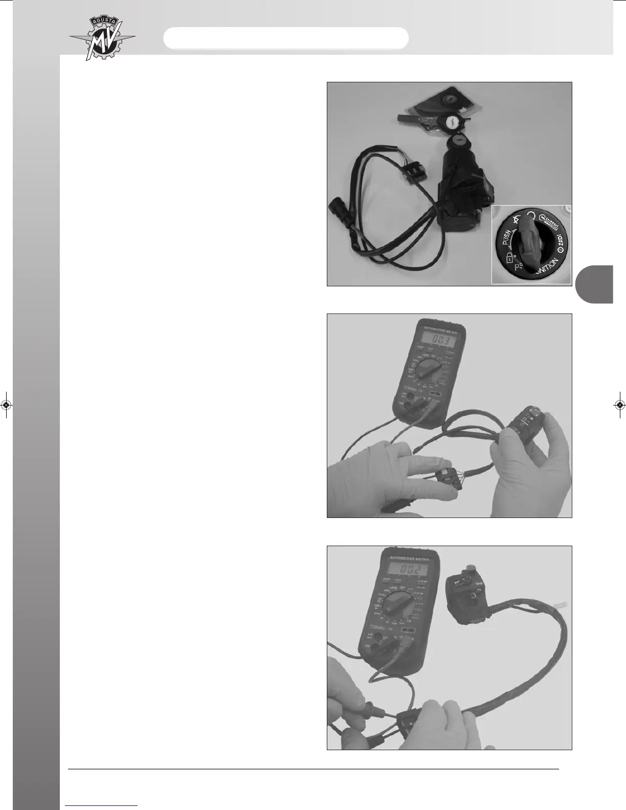
KEY SWITCH
Whenever the dashboard, with the switch on the ON
position, is not powered, first check the conditions of
the fuse located on the start-up remote switch under
the seat and, if this should be in good condition, check
the conditions of the fuse located in position 1 on the
fuse box.
Check these two conditions; if the defect remains,
check continuity between pins 3 and 4 of the key block
connector.
 Loading...