- 44 -
Frame
G
Carry out the sequence of operations of assembly in
reverse order to removal for the correct assembly of
the frame to the motorcycle.
Tighten the various fixings to the torque pressure
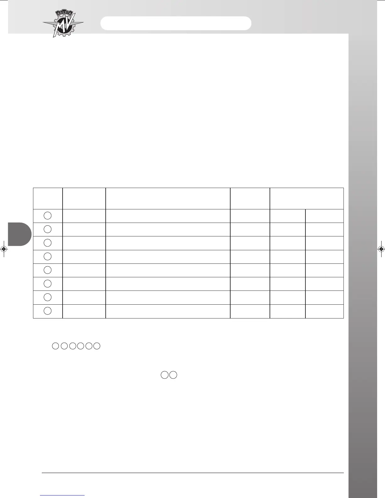
shown in the following diagram.
PART. DESIGN NO. DESCRIPTION DIM. TORQUE PRESSURE
N·m Kgm
1 8000B3004 Front engine mounting screw M12x1,25 55/60 5,5/6,0
2 8000B3561 Upper engine mounting screw M12x1,25 55/60 5,5/6,0
3 8000B2756 Lower engine mounting screw M12x1,25 55/60 5,5/6,0
4 8000B2750 Plate – frame screw M12x1,25 55/60 5,5/6,0
5 8000B2751 Front fork pin screw M15x1,25 70/75 7,0/7,5
6 8000B2755 Rear suspension compensator screw M10x1,25 45/50 4,5/5,0
7 8D00B2690 Plate – lower sub-frame fixing screw M8x1,25 24/28 2,4/2,8
8 8E00B2690 Plate – lower sub-frame fixing screw M8x1,25 24/28 2,4/2,8
The tightening of the engine mounting screws and the
plates 123456 is effectuated with the motor-
cycle resting on its wheels and the engine hanging
from the frame.
The tightening of the rear sub-frame screws 7 8 is
carried out by letting the sub-frame drop into position
by its own weight.
Utilise AGIP GREASE 30 for the screws.












 To Next Page