Do you have a question about the Nikon A1 and is the answer not in the manual?
Steps for powering on the motorized stage, piezo Z stage, halogen lamp, mercury lamp, and microscope.
Procedure for turning on the laser.
How to power on the microscope controller.
Steps to initiate the computer system.
Instructions for launching the NIS-Elements software.
Operating the Ti Remote Control Pad for microscope adjustments.
Setting microscopy components like optical path, filters, and condensers.
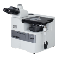
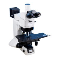
Description of controls on the Ti-E microscope main body.
Operating the HG Controller for fluorescence microscopy.
How to operate the joystick for stage movement and focus.
Operating the Perfect Focus System using the front panel.
Detailed operation of the A1 remote controller.
Steps to launch the NIS-Elements software for image capture.
Procedures for sample observation and microscope setup.
Switching the optical path to the A1 system.
Resetting interlocks and enabling laser oscillation.
Selecting the desired scan mode (e.g., Galvano).
Configuring optical paths for confocal image acquisition.
Setting up acquisition parameters and capturing images.
Instructions for saving acquired images.
Setting up channel series for multistained imaging.
Setting acquisition parameters and capturing multistained images.
Saving multistained images.
Accessing the Scan Area window.
Defining the area for zoom magnification.
Rotating the scan area for specific imaging.
Re-adjusting acquisition parameters using the Live function.
Accessing the Scan Area window.
Defining the Region of Interest (ROI) for scanning.
Adjusting acquisition settings with live image feedback.
Setting the Z-axis range for image acquisition.
Acquiring images across multiple Z-planes.
Opening the dialog for Z-intensity correction.
Setting Z position and adjusting brightness.
Registering parameters for each Z position.
Generating a 3D image from Z-series data.
Saving 3D images from specific viewpoints.
Creating a rotating movie of a 3D image.
Generating slice or projection views from Z-series.
Configuring settings for time-lapse imaging.
Performing time-lapse image acquisition.
Accessing and displaying the time measurement tool.
Defining Regions of Interest for measurement.
Executing time-based measurements and generating graphs.
Guidance on utilizing the time measurement features.
Defining areas for photo activation.
Configuring laser settings for photo activation.
Setting time-lapse parameters for simultaneous photo activation.
Switching between different image channels for display.
Navigating and displaying multidimensional image data.
Adding a scale bar to images.
Displaying acquisition metadata on images.
Methods for saving images, including special cases.
Retrieving acquisition parameters from saved images.
Accessing microscope control status from acquired images.
Adjusting image contrast and brightness using LUTs.
Procedure for closing the NIS-Elements software.
Steps to safely power down the laser unit.
Steps to safely power down the microscope controller.
Sequence for powering down the microscope main body.
Steps to properly shut down the computer.
Launching the NIS-Elements software for spectral imaging.
Sample observation and microscope setup procedures.
Switching the optical path to the A1 system for spectral imaging.
Resetting interlocks and enabling laser oscillation.
Configuring optical paths for spectral image acquisition.
Setting acquisition parameters for spectral images.
Saving spectral images.
Performing spectral unmixing using ROI data.
Preparing reference spectral data for live unmixing.
Executing live spectral unmixing on the sample.
Launching NIS-Elements software for virtual filter imaging.
Sample observation and microscope setup procedures.
Switching the optical path to the A1 system.
Resetting interlocks and enabling laser oscillation.
Configuring optical paths for virtual filter image acquisition.
Setting acquisition parameters for virtual filter images.
Saving virtual filter images.
Defining multiple image acquisition points.
Acquiring time-lapse images at multiple points.
Pre-configuring Z-stack settings for large images.
Defining the area for capturing large images.
Configuring advanced settings for large image acquisition.
Setting the method for focusing during large image capture.
Configuring save options and acquiring large images.
Selecting the resonant scan mode.
Setting acquisition parameters for high-speed imaging.
Saving high-speed images.
Opening the ND Acquisition dialog box.
Setting the Z-axis acquisition range for ZT series.
Configuring time-lapse settings for ZT series.
Initiating ZT series image acquisition.
Defining areas for photo activation.
Configuring laser settings for photo activation.
Setting time-lapse for simultaneous photo activation imaging.
| Type | Confocal Microscope |
|---|---|
| Software | NIS-Elements |
| Laser Lines | 405 nm, 488 nm, 561 nm, 640 nm |
| Detector | GaAsP PMT detectors |
| Imaging Modes | Confocal, Spectral, FRAP |
| Scanning Method | Galvanometer-based scanning |
| Objectives | Compatible with Nikon CFI objectives |
| Dimensions | Varies with configuration |
| Weight | Varies with configuration |
| Laser | Multiple laser lines available |