Interface Configuration Guide 7705 SAR Interfaces
Edition: 01 3HE 11011 AAAC TQZZA 149
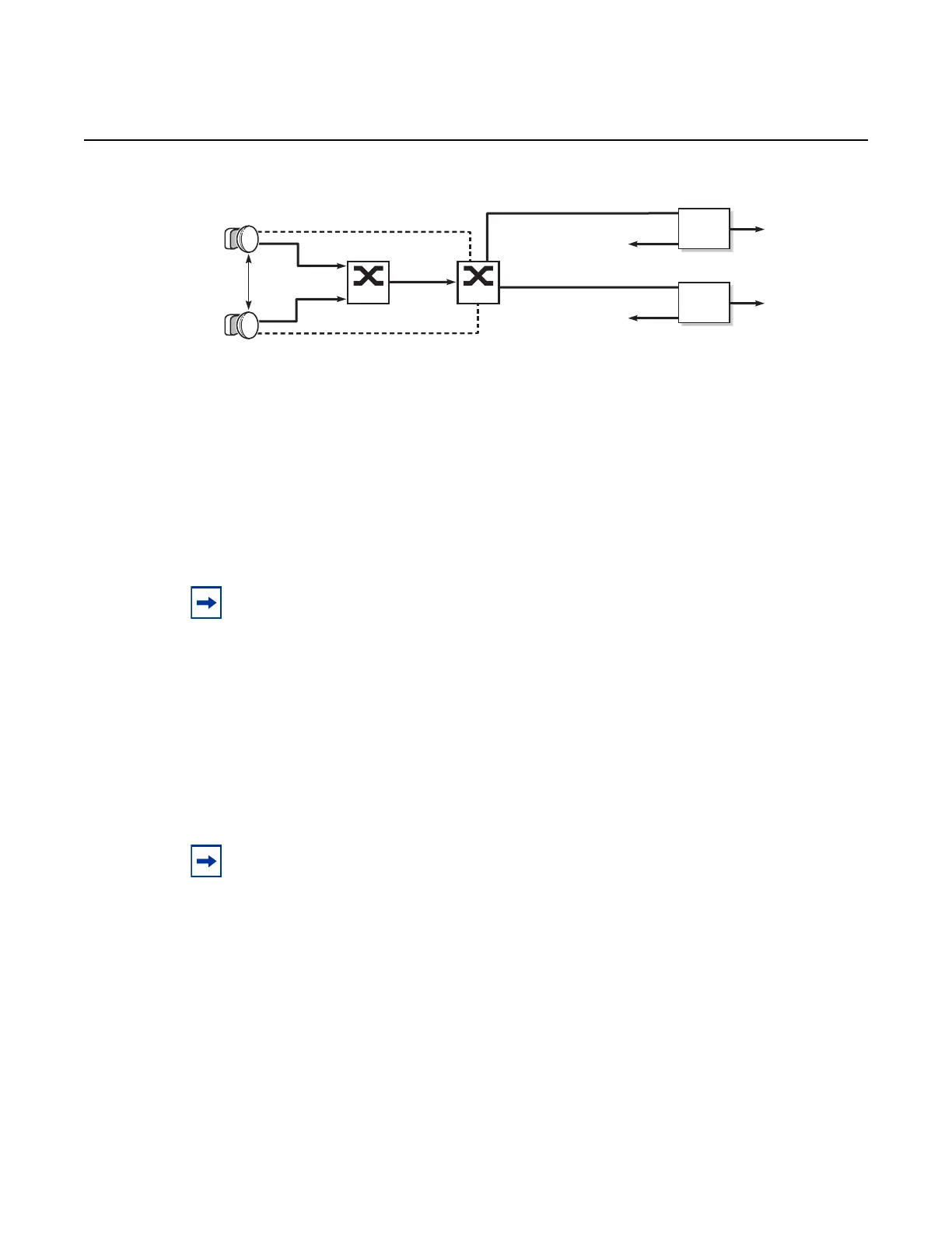
Figure 17 Example of a TDA Application
Communication Method Between the Main and Spare MPR-e Radio
In a 1+1 HSB configuration, the communication path between the main (active) and
spare (standby) MPR-e radios installed on a tower is set up using a tight cable.
3.2.17.3.4 1+1 Switching Operation
The following list defines the types of EPS, TPS, and RPS MPR-e radio switching
operations that can be enabled using the tools>perform>mw>link command. Refer
to the 7705 SAR OAM and Diagnostics Guide, “Tools Command Reference”, “Tools
Perform Commands”, for more information.
• lockout—prevents the spare MPR-e radio from ever becoming the main radio,
even when the main MPR-e radio fails; this operation overrides any forced,
automatic, or manual operation
• forced —forces the spare MPR-e radio to become the main MPR-e radio, even
though it might not be in a fit state to assume the role. A forced switch operation
overrides any automatic or manual switch operation that is in place.
diplexer
To Rx MPT main*
diplexer
To Rx MPT spare*
SwitchSwitch
Main
antenna
Diversity
antenna
Antenna control
TPS control
25879
*signal is split to both MPT radios
in controller applications
Note: A tight cable is required with MPT-HC V2, MPT-XP, MPT-HLC, and MPT-QAM radios
(1+ 1 HSB is not supported on MPT-MC radios).
Note: TDA switching operation is enabled via the MCT.