2 Assembly and installation
BU 0200 en-3118 69
Pos: 162. 1 / Anlei tu ngen /El ektr oni k/F U un d St art er/ 2. M ont age un d Ins tal lati on/ Ele ktr isch er A nsc hl uss/ SK 1 xxE , SK 2x xE, SK xxxE-FDS /Ste uerteil /Det ails Ste uera nschl üsse (Samml ung) /Detail s Steu eransc hlüs se_00 _Tab ellen kopf_[ SK 1xxE , SK 2xxE] @ 7\mod_1435561812889_388.docx @ 228818 @ @ 1
Description / Technical data
Function of factory setting
Pos: 162. 2 / Anlei tu ngen /El ektr oni k/F U un d St art er/ 2. M ont age un d Ins tal lati on/ Ele ktr isch er A nsc hl uss/ SK 1 xxE , SK 2x xE, SK xxxE-F DS /Ste uer teil/ Det ail s St eu erans chl üss e ( Sam mlu ng) /Det ails St euer ansc hlüs se _01 _DOU T [ SK 1x0E, SK 2 xxE] @ 7\ mod_1435562956782_388.docx @ 229138 @ @ 1
Signalling of device operating statuses
With inductive loads: Provide protection
via free-wheeling diode!
Pos: 162. 3 / Anlei tu ngen /El ektr oni k/F U un d St art er/ 2. M ont age un d Ins tal lati on/ Ele ktr isch er A nsc hl uss/ SK 1 xxE , SK 2x xE, SK xxxE-F DS /Ste uer teil/ Det ail s St eu erans chl üss e ( Sam mlu ng) /Det ails St euer ansc hlüs se _01 _DOU T_ Erg änz ung [SK 2x xE] @ 7\ mod_1435562960093_388.docx @ 229170 @ @ 1
Size 4: Max. load 50 mA
SK 2x5E: Voltage level depending on input voltage level (18 – 30 V DC)
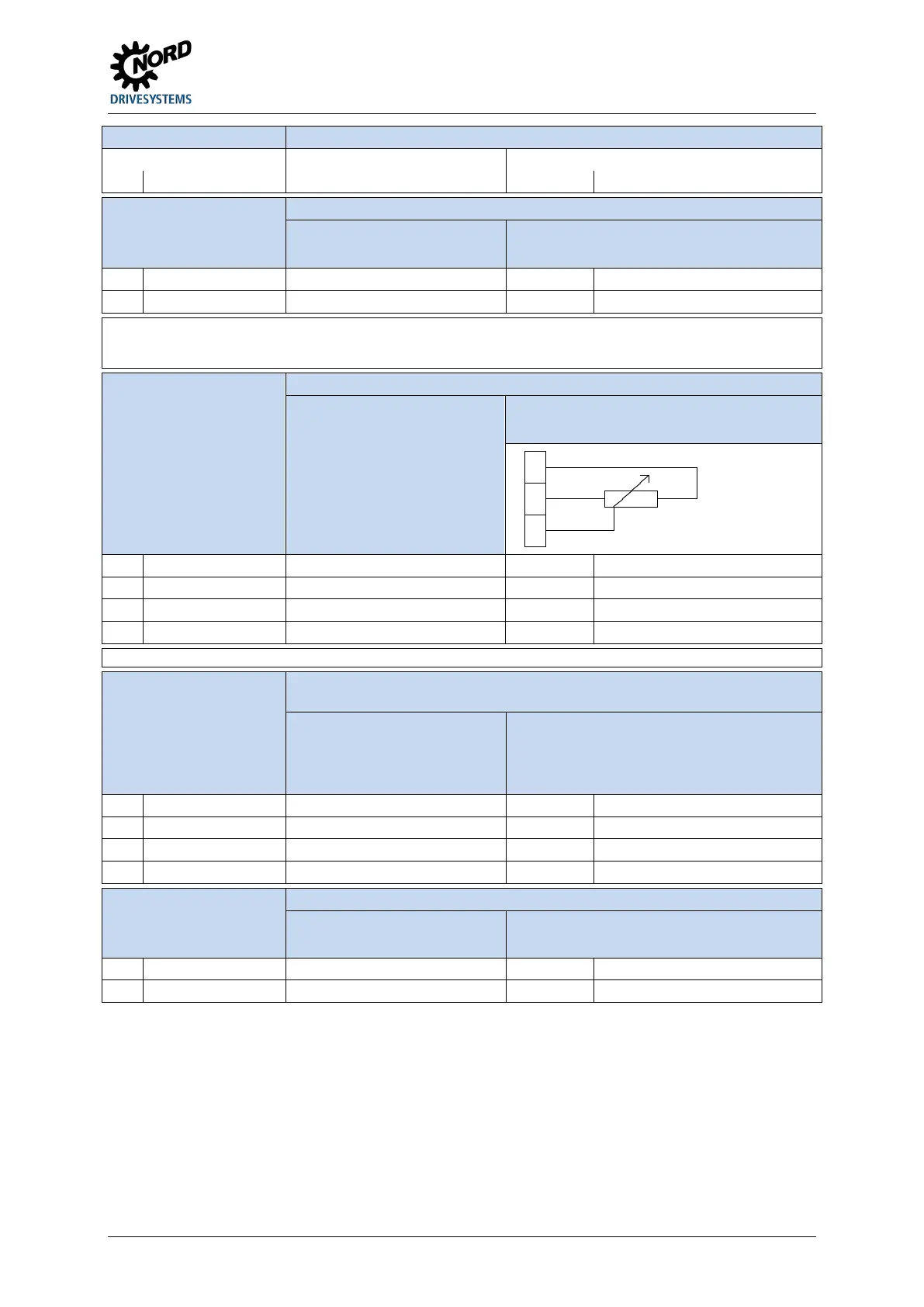
Pos: 16 2.4 /A nleitu ngen/ Elektr onik /FU und St art er/2. Montage und Inst allation/Elektr ischer Anschl uss/SK 1xxE , SK 2 xxE, SK xxxE-FDS /Steuer teil /Det ails Ste uera nschlüs se (S ammlu ng)/D etail s Steuer ansc hlüss e_02 _AIN [SK 1x0E, S K 2x0E] @ 7\ mod_1435563256730_388.docx @ 229266 @ @ 1
Actuation of device by external controller, potentiometer or the like.
Resolution 12Bit
U= 0 …10 V, R
i
=30 kΩ
I= 0/4 … 20 mA
Burden resistance (250 Ω) via DIP switch
AIN1/2
Maximum permissible voltage at
analogue input: 30 V DC
Matching of the analogue signals is performed via P402 and
P403.
+ 10 V Reference voltage: 5 mA not short-circuit resistant
11
40
14
AIN1+ Analogue input 1 P400 [-01] Setpoint frequency
GND Reference potential GND - -
Pos: 16 2.5 /A nleit ung en/ Ele ktr onik /FU und St art er/2 . M ontag e u nd I nst alla tio n/El ek tris cher Ansc hl uss/ SK 1xx E, S K 2 xxE, S K xx xE-FD S/St euert eil/D etails Steuer ansc hlüsse (Samml ung )/Detai ls St euerans chlüs se_ 02_AIN _Erg änzung [SK 2x0 E] @ 7\mod_1435563260457_388.docx @ 229298 @ @ 1
NOTICE: SK 200E and SK 210E: Terminal 12 must be used instead of terminal 40 (AGND/0V)
Pos: 162. 6 / Anlei tu ngen /El ektr oni k/F U un d St art er/ 2. M ont age un d Ins tal lati on/ Ele ktr isch er A nsc hl uss/ SK 1 xxE , SK 2x xE, SK xxxE-F DS/ Ste uertei l/D etai ls Steu eransc hlüs se (Sam mlung )/Det ails St euera nschl üsse _03_DIN [SK 2 xxE] @ 7\mod_1435562625904_388.docx @ 229010 @ @ 1
Actuation of device via an external controller, switch or the like, connection of HTL
transmitter (DIN2 and DIN3 only)
as per EN 61131-2, type 1
Low: 0-5 V (~ 9.5 kΩ)
High: 15-30 V (~ 2.5 - 3.5 kΩ)
Scan time: 1 ms
Reaction time: 4 - 5 ms
10 nF (DIN1, DIN 4)
1.2 nF (DIN 2, DIN 3)
DIN 2 and DIN 3 double allocation
Min.: 250 Hz, Max.: 205 kHz
DIN1 Digital input 1 P420 [-01] ON right
DIN3 Digital input 3 P420 [-03] Fixed frequency 1 ( P465[-01])
Pos: 16 2.7 /A nleitu ngen/ Elektr onik /FU und St arter/2. M ontage und I nstallation/ Elektrischer Ansc hluss/SK 1 xxE, SK 2xxE, SK xxxE-FDS /Ste uertei l/Det ails St euera nschl üsse (Samml ung) /Detail s Steu eransc hlüs se_04 _TF [S K 1xxE, SK 2xxE] @ 7\mod_1435563263847_388.docx @ 229330 @ @ 1
Monitoring of motor temperature using PTC
If the device is installed near the motor, a
shielded cable must be used.
The input is always active. In order to make the device
operational, a temperature sensor must be connected or both
contacts must be jumpered.
TF- PTC resistor input - -
Pos: 162. 8 / Allg em ein/ Allg emei ng ültig e M od ule /---------Seitenumbruch kompakt --------- @ 13\mod_1476369695906_0.docx @ 2265495 @ @ 1

 Loading...


