Routing and splicing the fiber cable 7-39
AccessNode Series 800A Outside Plant Cabinet Installation 323-3001-210 Issue 1.0
Procedure 7-4 (continued)
Routing fiber to the ABM when no FPP is installed
Step Action
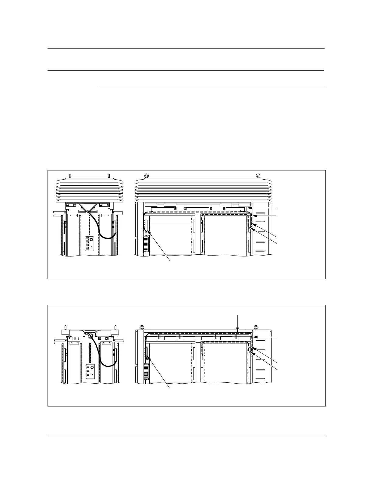
6 Route tubing across the ceiling of the cabinet as per the type of roof assembly
on the rear side of the air baffle (see Figure 7-20 or Figure 7-21).
Note 1:
For the heat exchanger roof, route the fiber inside the V-baffle
enclosure (see Figure 7-20).
Note 2:
The air induction roof has a cable hooks for all cable routing (see
Figure 7-21).
7 Tie wrap the fiber cable to the cabinet ceiling as per the type of roof assembly.
Figure 7-20
Tie wrap the fiber cable to the ceiling of the heat exchanger roof assembly
FW-15144
Figure 7-21
Tie wrap the fiber cable to the ceiling of the air induction roof assembly
FW-15145
—continued—
Rear view
Maintain at least
minimum bend
radius
3.0 in. (76 mm)
Swing frame cutout
Left inside view
V- trough
TerminationFrontRear AC
FW-15144
Service loop
ABM
Fiber patch cords
Rear view
Maintain at least
minimum bend
radius
of 3.0 in. (76 mm)
Swing frame cutout
Left inside view
TerminationFrontRear AC
FW-15145
Plastic cable duct
Service loop
Fiber patch cords
ABM