Provisioning the external alarms 8-7
AccessNode Series 800A Outside Plant Cabinet Installation 323-3001-210 Issue 1.0
Procedure 8-2 (continued)
Wiring customer reserved optional defined external alarms
Step Action
5 Dress and tie-wrap all installed alarm cabling.
6 Remove all combustible materials from the cabinet.
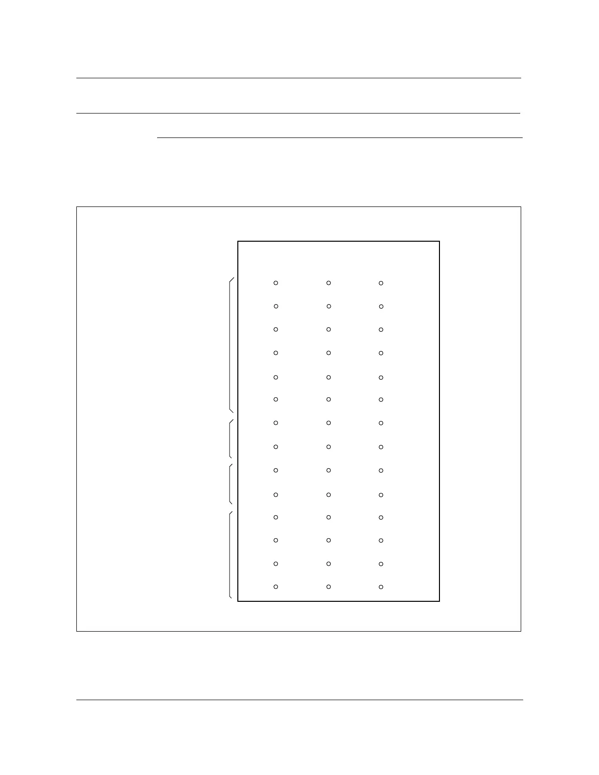
Figure 8-1
BIP wire-wrap block pin field layout and connections
FW-15150
Note: For the NT4K14BA BIP the pinfield above is rotated 90˚ clockwise.
—end—
R01 RRET R02
R03 RRET R04
R05 RRET R06
1
4
7
10
13
16
19
22
25
28
31
34
37
40
R07 RRET R08
R09 RRET R10
R11 RRET RRET
T15 TRET T16
T17 TRET T18
OWTIP OWBUZ ACOSW
OWRING OWBUZR ACOSWR
CRAUD MJAUD MNAUD
CRAUDR MJAUDR MNAUDR
CRVIS MJVIS MNVIS
CRVISR MJVISR MNVIS
3
6
9
12
15
18
21
24
27
30
33
36
39
42
PIN #
PIN #
E2A
receive
E2A
transmit
Orderwire
connections
Office
alarms
FW-15150