9-28 Installing and connecting the batteries
AccessNode 323-3001-210 Issue 1.0
Procedure 9-3 (continued)
Wiring the cabinet when the batteries are installed in the battery vault
Step Action
3 Strip the battery cable ends approximately 1/2 in. (1.27 cm) and crimp 6 AWG
terminal lugs onto each battery cable lead.
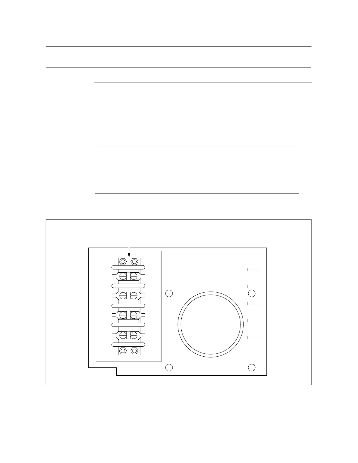
4 Connect the battery cable lugs to TB13 as shown in Table 9-11 and
Figure 9-14.
Figure 9-14
TB13 close-up view
FW-15157
—continued—
Table 9-11
Battery lead connections to TB13
Battery lead TB13 terminal designation
Battery 1 (RED) TB1, DC shf -48V Batt 3 (RED)
Battery 2 (RED) TB2, DC shf -48V Batt 4 (RED)
Battery 1 Return (BLK) TB3, DC shf BR Batt 3 (BLK)
Battery 2 Return (BLK) TB4, DC shf BR Batt 4 (BLK)
Batt 1
-48v
RED
Batt 2
-48v
RED
Batt 1
BR
BLK
Batt 2
BR
BLK
DC shf
-48V
Batt 3
RED
DC shf
-48V
Batt4
RED
DC shf
BR
Batt 3
BLK
DC shf
BR
Batt 4
BLK
TB13 terminal block
FW-15157