G3 Series EtherNet/IP
TM
DLR Technical Manual
15-145
TDG3EDM1-6EN 3/18
Subject to change without notice
www.asco.com/g3
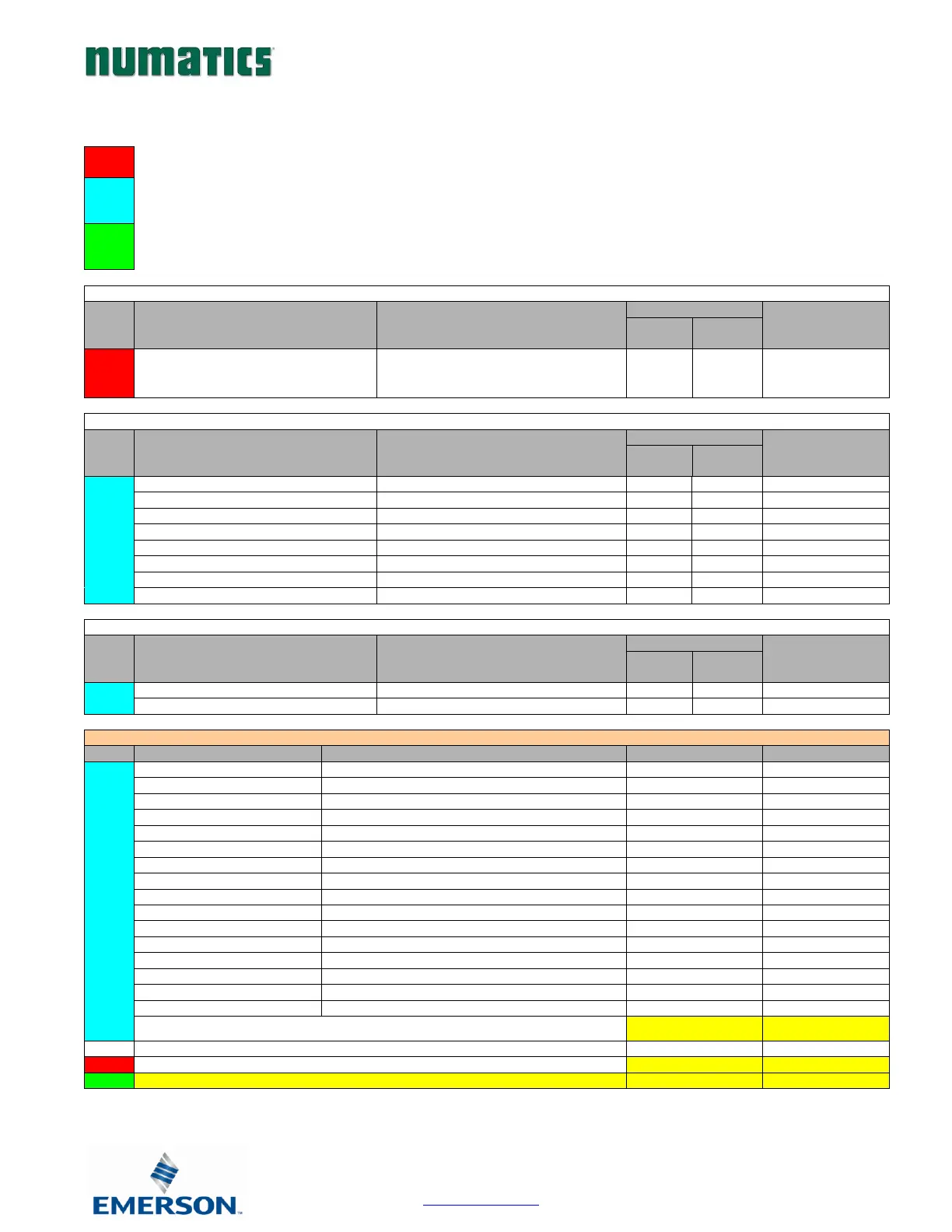
15.2 Manifold and I/O Data Sizing Worksheet
: Choose appropriate value and place the corresponding Input and Output values in the boxes labeled, “Valve Byte
Requirements” at the bottom of the page
: Choose up to sixteen modules to be included on the discrete I/O side of the manifold and place sum of the
corresponding input bytes and output bytes in the boxes labeled, “Sub-Bus Byte Requirements” at the bottom of
the page.
: Total the input bytes and output bytes values from the boxes labeled “Sub-Bus Byte Requirements” and “Valve
Byte Requirements” in the boxes labeled “Total Input and Output Bytes for Manifold. This is the total input and
output byte values required for the configured manifold.
16 Inputs - Terminal Strip
8 Inputs / 8 Outputs - 8 x 12mm
High Current 8 Outputs – 8 x 12mm
Total Input/Output Size Calculation
Sub-Bus Byte Requirements:
Optional Diagnostic Word:
Total Input and Output Bytes for Manifold