• The UNSW POWER screen indicates the voltage level present on the UNSW
(Node & Input) power pins (Pin No. 2 and 3) of the main power connector.
•
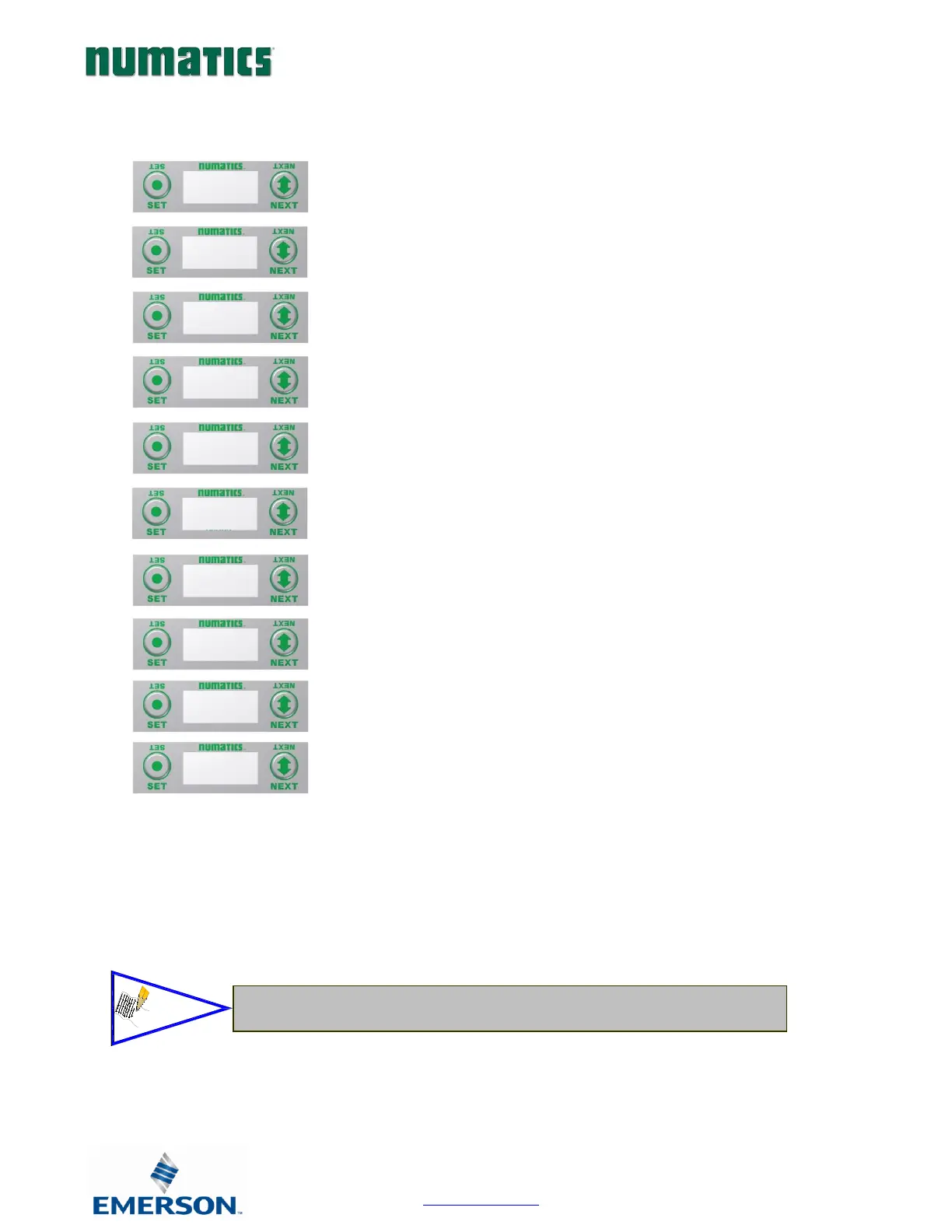
1. Press the SET button to enter Diagnostic sub-
menu.
2. Press the NEXT button to scroll through the
a. SET SELF TEST
i. - Please see following page for
description
b. USNW POWER
i. - Displays voltage level of un-switched
power (Node & Inputs)
c. NETWORK DATA
i. - Displays the network diagnostics
d. FIRMWARE REVISION
i. - For service personnel
e. FIRMWARE BUILD
i. - For service personnel
f. LOAD FIRMWARE
i. - For service personnel
g. BOOTCODE REVISION
i. - For service personnel
h. BOOTCODE BUILD
i. - For service personnel
i. PART NUMBER
i. - Displays replacement part number of
module
j. RETURN TO MAIN MENU