2. G3 Introduction
The G3 Series is an electronic product platform that features an integrated graphic display for simple commissioning and
displaying of diagnostic information. The G3 offers innovative distribution capability which allows the same I/O components
that make up a centralized manifold configuration to be used as the distribution components as well, decreasing the need for
duplicate components on centralized and distributed applications. The G3 platform interfaces to a variety of valve series and
fieldbus interface protocols and can address a total of 1200 I/O points (150 bytes). With proper assembly and termination, the
G3 modules will have an IP65 / IP67 rating.
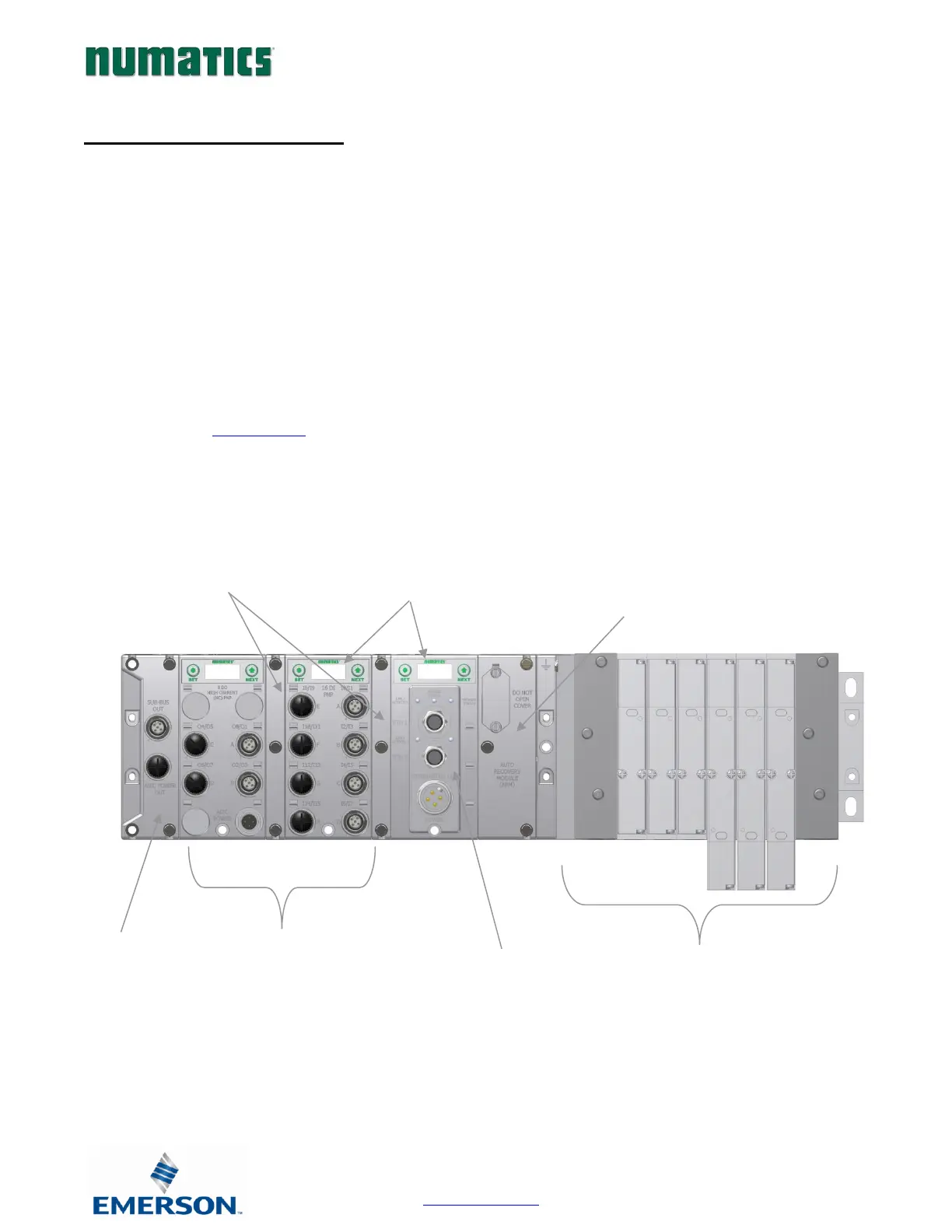
The manifold can be viewed as having two sections to it, the Valve Side and the Discrete I/O Side. The Valve Side
supports a maximum of 128 solenoid coils and the Discrete I/O Side supports a maximum of 16 modules capable of
addressing up to 1200 outputs, 1200 inputs or various combinations.
Various discrete modules with integrated graphic display are available. They include digital I/O, analog I/O, and
specialty modules which cover various application needs. Pin-outs for all connectors are labeled on the side of the
respective modules and are also detailed in the module section of this document.
This manual details specific information for configuring and commissioning the Numatics G3 Series product line. For
more information relating to pneumatic valves and valve manifold assemblies, please refer to the Numatics “In Control
“catalog at www.asco.com.