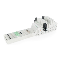
The analog I/O modules follow the same rules as the digital I/O modules. The maximum total number of
modules on the Sub-Bus is 16. The analog boards allow the user to control devices using an analog
signal. The analog modules also allow the user to relay analog information from input devices. These
modules are available in two analog signal types: 0-10 V and 4-20 mA. These two signal types are
offered in two different I/O configurations: 2 analog input channels/ 2 analog outputs channels and 4
analog input channels.
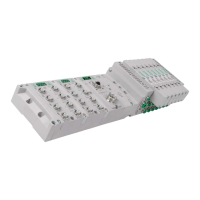
Four I/O - 12mm Female Modules
Specifications
- Input Resolution: 16 bit (65,536 Counts),
- Output Resolution: 16 bit (65,536 Counts)
- Settling Time: 3 ms Max
- Absolute Precision: ≤ 1.0% of Scale
- Voltage Input Impedance: 0-10VDC – 40K Ohms
- Current Input Impedance: 250 Ohms
- Input Cutoff Frequency: 100 Hz