EasyManua.ls Logo

Numatics G3 Series - Distribution System and Components; Distribution of I;O Capability

Numatics G3 Series
164 pages
Print Icon
To Next Page IconTo Next Page
To Previous Page IconTo Previous Page
Loading...
G3 Series EtherNet/IP
TM
DLR Technical Manual
6-51
TDG3EDM1-6EN 3/18
Subject to change without notice
www.asco.com/g3
7. Distribution
Example 1
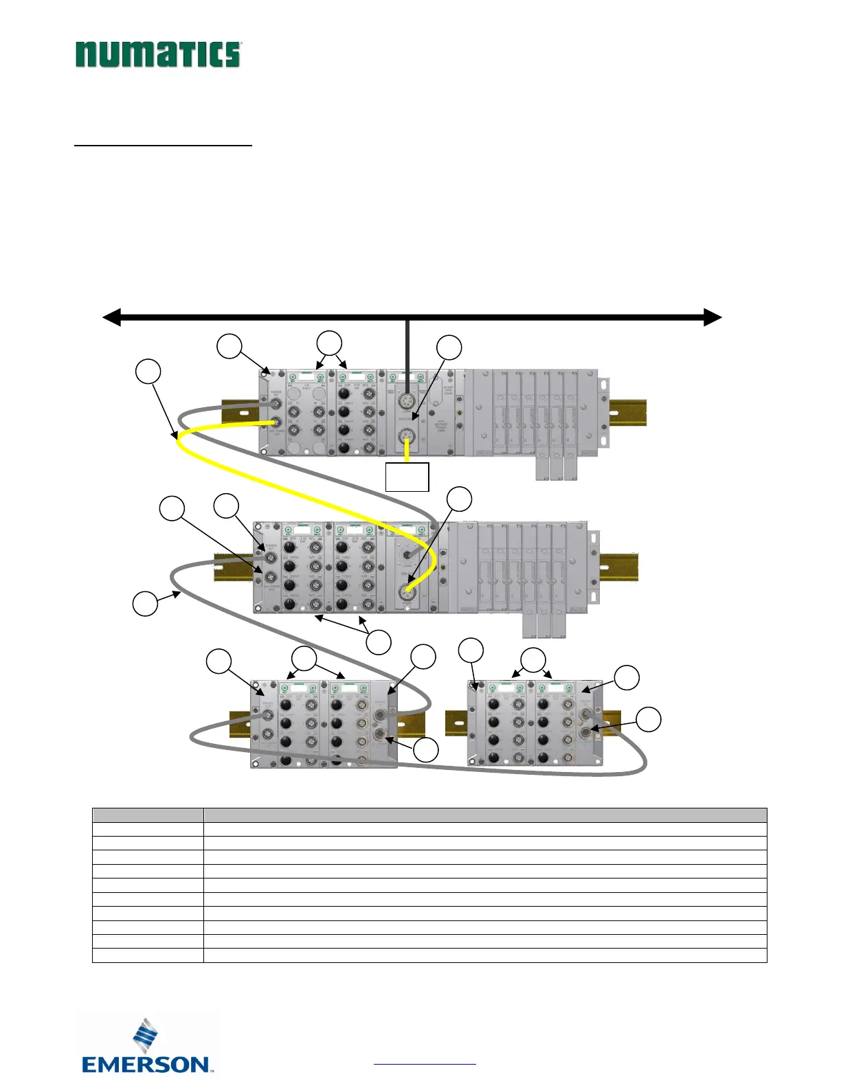
Distribution of I/O capability can be easily achieved with the G3 platform by means of Sub-Bus modules.
I/O modules, valve manifolds and/or a combination of both can be simply separated from the main
manifold and distributed via a sub-bus communication cable. The G3 platform uses the same I/O
modules on the main manifold as on the distribution chain. The main communication module can control
up to 16 I/O modules either on the main manifold or as part of the sub-bus connections. To utilize the
sub-bus distribution capabilities the Sub-Bus OUT module must be located on the end of the main
communication manifold and a Terminator Module must be located at the last sub-bus component.
Detail No.
Description
1
Main Communication Module (Node)
2
Sub-Bus Power Cable (Can be connected to separate power supply for isolated power control )
3
Distributed Sub-Bus Valve Module
4
Sub-Bus IN module
5
Sub-Bus OUT module
6
Sub-Bus Communication Cable
7
I/O Modules
8
Terminator Module (Used to terminate sub-bus)
9
Aux. Power IN (Used to augment Input power and/or supply power to Output modules)
10
Aux. Power OUT (Can be used to supply power to distributed modules)
Fieldbus network
4
5
3
6
8
Distributed
Sub-Bus I/O
Modules
1
2
Main Fieldbus
Valve Manifold
with I/O
Distributed Sub-
Bus Valve
Manifold
with I/O
Power
Supply
7
7
5
5
4
7
7
10
9
9

Table of Contents

Related product manuals