G3 Series EtherNet/IP
TM
DLR Technical Manual
16-161
TDG3EDM1-6EN 3/18
Subject to change without notice
www.asco.com/g3
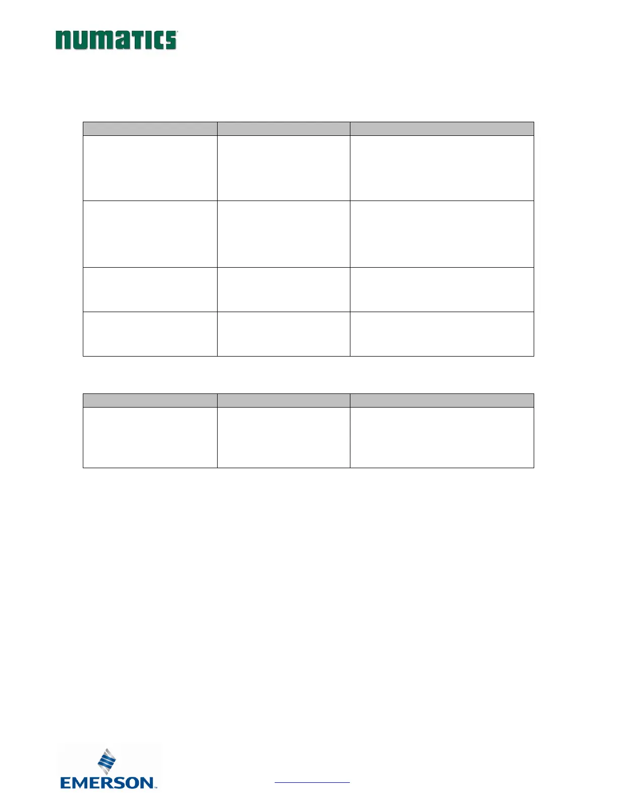
16.3 Troubleshooting
Communication Node
The wrong valve solenoid coils
are being energized.
Z-Board
TM
type mismatch.
Single Z-Board
TM
present
where double Z-Board
TM
expected or vice versa.
Check that correct Z-Board
TM
types are
installed. Check that ribbon cable
(Output group No. 2) is connected to
appropriate valve station.
See page 147 for bit mapping rules
Valve outputs do not energize.
Output power not present or
connected improperly on
Auxiliary Power connector.
Check for 24VDC on the +24 VDC (Valves
and Outputs) pin of the MINI Auxiliary
Power connector of the Comm. module.
Unable to go to the manifold’s
web page.
Bad cabling, incorrect
computer settings, etc.
Verify the type of cable (straight-thru or
crossover) that is being used. Also, verify
the wiring of the cable.
Outputs remain on when
communication is lost and/or
PLC is in “Program” mode.
Communication Fault
parameters are set incorrectly.
See page 138.
Check the communication fault/idle mode
parameter setting to ensure that it is not
set to “Hold Last Output State”.