DMTA-20015-01EN [U8778402], Rev. J, January 2014
Connector References
119
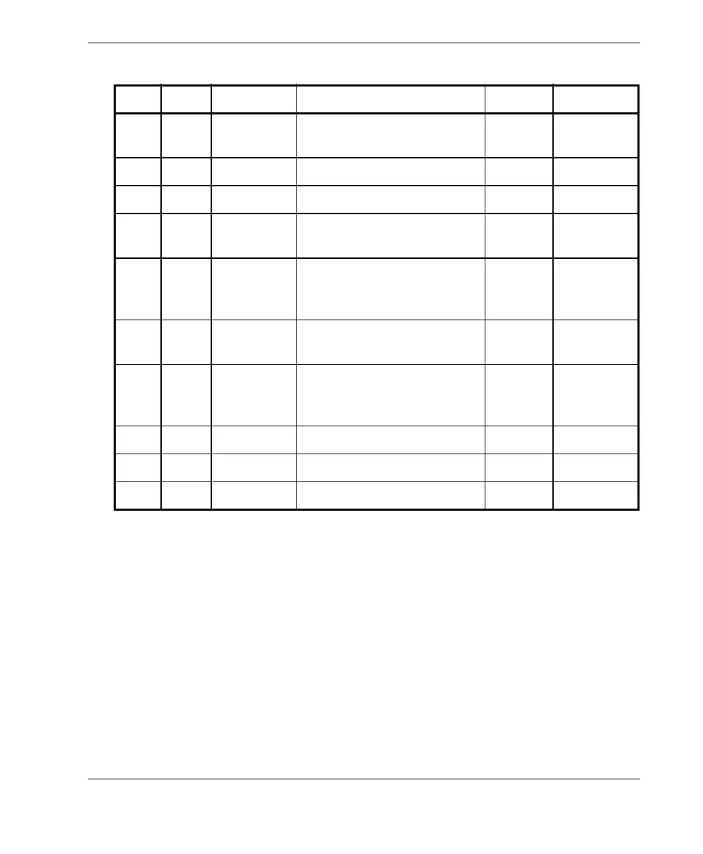
6OutDOUT1/
PaceOut
Digital out 1/pace output ±15 mA TTL
7 In RRX Rx RS-232/485
8 Out RTX Tx RS-232/485
9 In PhA axis 1 Encoder 1:
phase A/clock / up/down.
TTL
10 In PhB axis 1 Encoder 1:
phase B/direction/N.U./
N.U.
a
TTL
11 In PhA axis 2 Encoder 2:
phase A/clock/up/down.
TTL
12 In PhB axis 2 Encoder 2:
phase B/direction/N.U./
N.U.
TTL
13 – Key
14 Out DOUT2 Digital output 2 ±15 mA TTL
15 – GND Ground
a. N.U. = Not used
Table 25 Pinout for the scanner interface connector (continued)
Pin I/O Signal Description Current Level