OMICRON 39
Setup and connection
For this purpose, CT Analyzer provides a "Delta Compensation" field on the CT-Object card where you
can select the delta compensation factor depending on the bushing terminals that are used for primary
signal measurement.
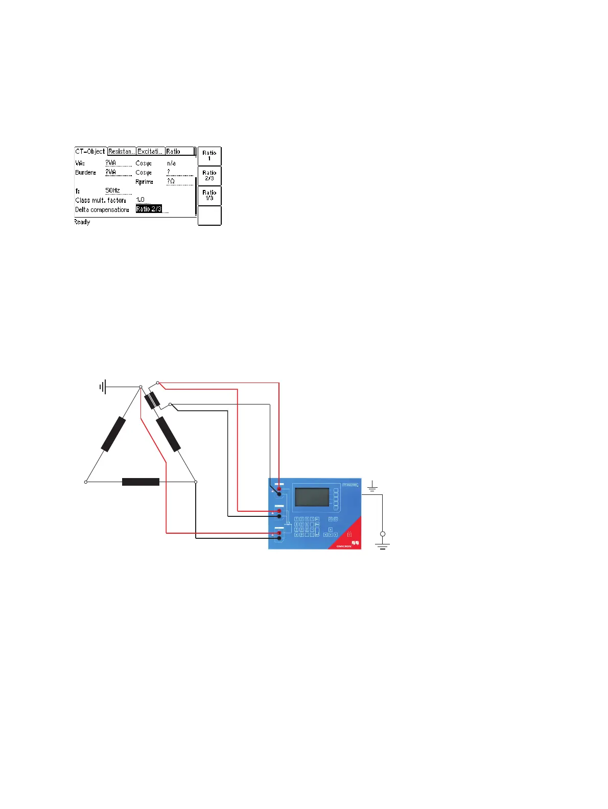
Figure 3-13: Setting the delta compensation on the CT-Object card
If it is possible to short-circuit the transformer winding at the same leg as the primary measurement is
done (see Figure 3-15), the measurement should be performed with the winding short-circuited. In this
case, no delta compensation is required since the voltage induced on the transformer’s secondary
winding is zero and thus the voltage induced on the primary side of the transformer is also zero.
For the measurement setup shown in Figure 3-14, the delta compensation factor on the CT-Object card
has to be set to "Ratio 2/3" (see Figure 3-13).
If input PRIM is connected between L1 and L2, the delta compensation has to be set to "Ratio 1/3".
Figure 3-14: Measurement setup for delta compensation "Ratio 2/3"
In the configuration shown in Figure 3-15, no delta compensation is required since the main winding of
the power transformer is short-circuited on the other side. This avoids the induction of flux in the main
winding of the power transformer that could influence the measurement results.