38
Memory Management Parameters
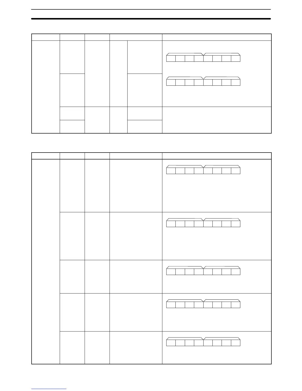
Axis Address R/W Name Description
Common
4100
R For
task 1
First position
data item no.
First position data item no.
Last position data item no.
0000x10
3
x10
2
x10
1
x10
0
L+1 L
4101 Last position
data item no.
Specifies the first and last numbers of position data
items for task 1 within a range of 0 to 1,999.
Teaching is possible in this range only.
0000x10
3
x10
2
x10
1
x10
0
L+1 L
4102
R For
task 2
First position
data item no.
Specifies the first and last numbers of position data
items for task 2.
range
between the position data items used for task 1 and
those used for task 2.
Mechanical Parameters
Axis Address R/W Name Description
X
4200 R Minimum unit setting
Specifies the minimum unit (i.e., the decimal position)
for the mechanical system.
X = 0 (1)
X = 1 (0.1)
X = 2 (0.01)
X = 3 (0.001)
X = 4 (0.0001)
0000000X
L+1 L
4201 R Display unit
Specifies the unit displayed with the MC Support
Software.
X = 0 (mm)
X = 1 (inch)
X = 2 (deg)
X = 3 (Pulse)
0000000X
L+1 L
4202 R Rotation direction
Specifies the rotation direction of the motor.
X = 0: CW with positive voltage.
X = 1: CCW with positive voltage.
0000000X
L+1 L
4203 R Emergency stop method
Specifies the method to stop the MC Unit
immediately.
X = 0: Instantaneous 0 V output.
X = 1: Pulse accumulation.
0000000X
L+1 L
4204 R Encoder ABS/INC
Specifies the type of encoder.
X = 0: INC encoder
X = 1: ABS encoder
0000000X
L+1 L
Details of Data Transmission and Reception Units
Section 4-4
 Loading...


