9 Using Expansion Units and Expansion I/O Units
9-16
CP1E CPU Unit Hardware User’s Manual(W479)
1
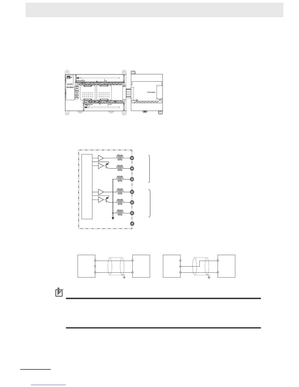
Connect the Analog Output Unit to the CPU Unit.
2
Wire to analog input devices.
(1) Wiring internal circuits of the CPU Unit
(2) Wiring analog input devices to the Analog Output Unit
Precautions for Correct UsePrecautions for Correct Use
• Connect the shield to the FG terminal to prevent noise.
• Separate wiring from power lines (AC power supply lines, high-voltage lines, etc.)
• When there is noise in the power supply line, install a noise filter on the input section and the
power supply.
CP1W-DA041
Analog Output Unit
CH
I OUT1 I OUT3
I OUT2
VOUT1
VOUT2
VOUT3
COM1
COM2
I OUT4
VOUT4
COM4
NC
AG
COM3
OUT
CP1E CPU Unit
Analog output 1
Analog ground
NC
I OUT1
COM1 (−)
V OUT1
I OUT4
COM4 (−)
V OUT4
Analog output 4
Internal circuits
to
to
+
V OUT
COM
I OUT
−
+
V OUT
COM
I OUT
−
Analog
output
unit
Analog
device
with
voltage
input
Analog
output
unit
Analog
device
with
current
input
2-core shielded
twisted-pair cable
2-core shielded
twisted-pair cable
FG FG

 Loading...


