9-17
9 Using Expansion Units and Expansion I/O Units
CP1E CPU Unit Hardware User’s Manual(W479)
9-2 Analog Output Units
9
9-2-4 Flow of Processing
Additional Information
When external power is supplied (when setting the range code), or when there is a power inter-
ruption, a pulse-form analog output of up to 1 ms may be generated.
If this causes problems with operation, take countermeasures such as those suggested below.
• Turn ON the power supply for the CP1E CPU Unit first, confirm correct operation, and then
turn ON the power supply for the load.
• Turn OFF the power supply for the load before turning OFF the power supply for the CP1E
CPU Unit.
3
Create the ladder program.
(1) Allocating Output Words
Four output word are allocated to the Analog Output Unit starting from the next word follow-
ing the last allocated word on the CPU Unit or previous Expansion Unit or Expansion I/O
Unit.
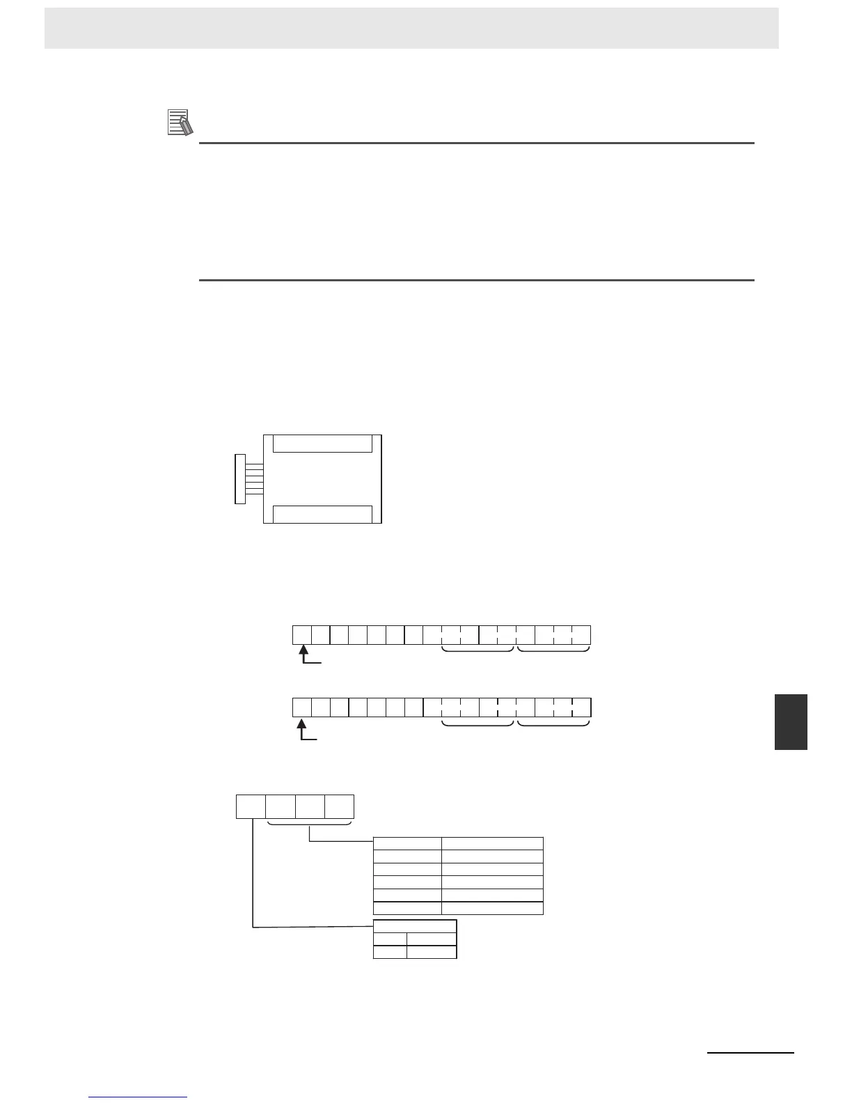
(2) Writing Set Data
Write the output use and the range code to words n+1 and n+2. The D/A conversion will
start when the set data is transferred from the CPU Unit to the Analog Output Unit.
• Set Data
• The Analog Output Unit will not start converting analog I/O values until the range code
has been written. The output will be 0 V or 0 mA.
Words n+1 to n+4
Analog Output Unit
15
1 0 0 0 0 0 0
876543210
Wd n+1
15
1 0 0 0 0 0 0
876543210
0
0
Analog output 2 Analog output 1
Analog output 4
Analog output 3
Set to 1.
Set to 1.
Wd n+2
0
1
Range code
Analog output signal range
−10 to 10 V
0 to 10 V
1 to 5 V
0 to 20 mA
4 to 20 mA
000
001
010
011
100
Output use
No
Yes

 Loading...


