9 Using Expansion Units and Expansion I/O Units
9-32
CP1E CPU Unit Hardware User’s Manual(W479)
(3) Reading Analog Input Conversion Values
The ladder program can be used to read the memory area words where the converted val-
ues are stored.
Values are output to the next two words (m + 1, m + 2) following the last input word (m) allo-
cated to the CPU Unit or previous Expansion Unit or Expansion I/O Unit.
(4) Writing Analog Output Set Values
The ladder program can be used to write data to the memory area where the set value is
stored.
The output word will be “n+1”, where “n” is the last output word allocated to the CPU Unit or
previous Expansion Unit or Expansion I/O Unit.
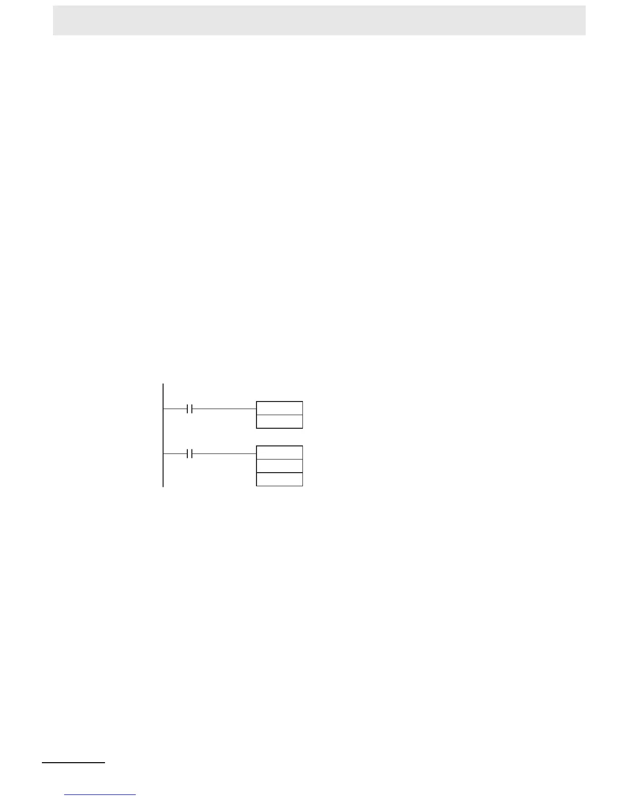
(5) Startup Operation
After the power is turned ON, it will require two cycle times plus approximately 50 ms before
the first conversion data is stored in the input words. Therefore, create a program as shown
below, so that when operation begins simultaneously with startup it will wait for valid conver-
sion data.
Analog input data will be 0000 until initial processing is completed. Analog output data will
be 0 V or 0 mA until the range code has been written. After the range code has been writ-
ten, the analog output data will be 0 V or 0 mA if the range is 0 to 10 V, -10 to 10 V, or 0 to
20 mA, or it will be 1 V or 4 mA if the range is 1 to 5 V or 4 to 20 mA.
(6) Handling Unit Errors
• When an error occurs in the Analog I/O Unit, analog input data will be 0000 and 0 V or 0
mA will be output as the analog output.
If a CPU error or an I/O bus error (fatal errors) occurs at the CPU Unit and the analog
output is set to 1 to 5 V or 4 to 20 mA, 0 V or 0 mA will be output. For any other fatal
errors at the CPU Unit, 1 V or 4 mA will be output.
• Expansion Unit and Expansion I/O Unit errors are output to bits 0 to 5 of word A436. The
bits are allocated from A436.00 in order starting from the Unit nearest the CPU Unit. Use
these flags in the program when it is necessary to detect errors.
MOV
2
D0
Always ON Flag
P_On
T5
#0002
T5
TIM 5 will start as soon as power turns ON.
After 0.1 to 0.2 s (100 to 200 ms), the input
for TIM 5 will turn ON, and the converted
data from analog input 0 that is stored in
word 2 will be transferred to D0.

 Loading...


