9-31
9 Using Expansion Units and Expansion I/O Units
CP1E CPU Unit Hardware User’s Manual(W479)
9-3 Analog I/O Units
9
9-3-4 Flow of Processing
3
Create the ladder program.
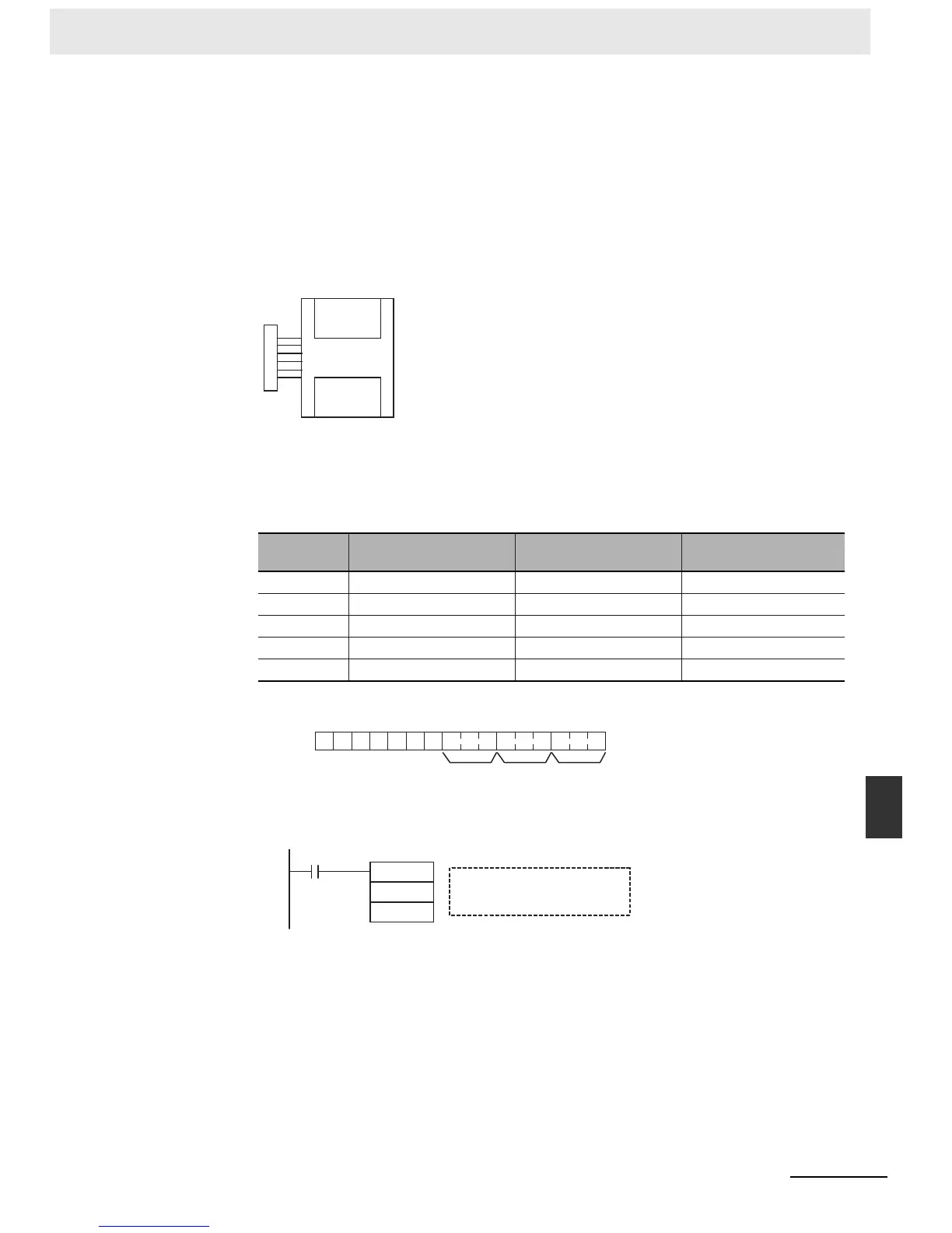
(1) Allocating I/O Words
Two input words and one output word are allocated to the Analog I/O Unit starting from the
next word following the last allocated word on the CPU Unit or previous Expansion Unit or
Expansion I/O Unit.
(2) Writing the Range Code
Write the range code to word n+1. A/D or D/A conversion begins when the range code is
transferred from the CPU Unit to the Analog I/O Unit. There are five range codes, 000 to
100, that combine the analog input 0 and 1 and analog output signal ranges, as shown
below.
• The Analog I/O Unit will not start converting analog I/O values until the range code has
been written. Inputs will be 0000, and 0 V or 0 mA will be output.
• After the range code has been set, 0 V or 0 mA will be output for the 0 to 10V, -10 to 10V,
or 0 to 20mA ranges, and 1 V or 4 mA will be output for the 1 to 5V and 4 to 20mA
ranges until a convertible value has been written to the output word.
• Once the range code has been set, it is not possible to change the setting while power is
being supplied to the CPU Unit. To change the I/O range, turn the CPU Unit OFF then
ON again.
Range code
Analog input 0 signal
range
Analog input 1 signal
range
Analog output signal
range
000 -10 to 10 V -10 to 10 V -10 to 10 V
001 0 to 10 V 0 to 10 V 0 to 10 V
010 1 to 5 V/4 to 20 mA 1 to 5 V/4 to 20 mA 1 to 5 V
011 0 to 5 V/0 to 20 mA 0 to 5 V/0 to 20 mA 0 to 20 mA
100 −−4 to 20 mA
Analog I/O Unit
Word m+1
Word m+2
32 inputs
16 outputs
Word n+1
word n+1
15
1 0 0 0 0 0 0
8 7 6 5 4 3 2 1
0
Analog
output
Analog
input 1
Analog
input 0
MOV
#800A
n+1
First Cycle Flag
A200.11
Analog input 0: 4 to 20 mA
Analog input 1: 0 to 10 V
Analog output: -10 to 10 V
Example: The following instructions set analog input 0 to 4 to 20 mA, analog input 1 to 0 to 10 V,
and the analog output to -10 to 10 V.

 Loading...


