9 Using Expansion Units and Expansion I/O Units
9-30
CP1E CPU Unit Hardware User’s Manual(W479)
Additional Information
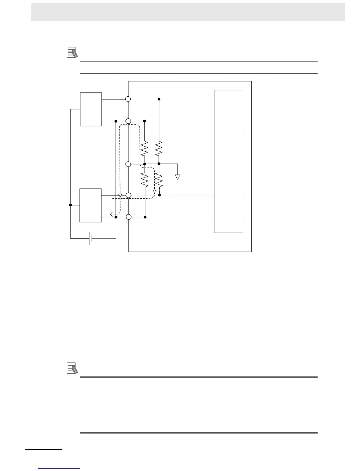
Refer to the following information on open circuits when using voltage inputs.
Example: If connected device 2 is outputting 5 V and the same power supply is being used for both
devices as shown above, approximately 1/3, or 1.6 V, will be applied to the input for input device 1.
If a wiring disconnection occurs when voltage input is being used, the situation described below will
result. Either separate the power supplies for the connected devices, or use an isolator for each input.
• If the same power supply is being used by the connected devices and a disconnection occurs at
points A or B in the above diagram, an unwanted circuit path will occur as shown along the dotted line
in the diagram. If that occurs, a voltage of approximately 1/3 to 1/2 of the output voltage of the other
connected device will be generated.
• If that voltage is generated while the setting is for 1 to 5 V, open-circuit detection may not be possible.
• If a disconnection occurs at point C in the diagram, the negative (-) side will be used in for both
devices and open-circuit detection will not be possible.
This problem will not occur for current inputs even if the same power supply is used.
Additional Information
When external power is supplied (when setting the range code), or when there is a power inter-
ruption, a pulse-form analog output of up to 1 ms may be generated.
If this causes problems with operation, take countermeasures such as those suggested below.
• Turn ON the power supply for the CP1E CPU Unit first, confirm correct operation, and then
turn ON the power supply for the load.
• Turn OFF the power supply for the load before turning OFF the power supply for the CP1E
CPU Unit.
24 VDC
A
CB
Analog
input
device 1
Analog
input
device 2
Internal
circuits

 Loading...


