21
CP1E CPU Unit Hardware User’s Manual(W479)
• Be sure that all the PLC terminal screws and cable connector screws are tightened to the torque
specified in the relevant manuals. The tightening torque for the terminals on the CP1W-
CIF11/CIF12 terminal block is 0.28 N·m Incorrect tightening torque may result in malfunction.
• Do not connect pin 6 (+5V) on the built-in RS-232C port on the CPU Unit or the RS-232C Option
Board (CP1W-CIF01) mounted to the CPU Unit to any external device other than the NT-AL001 or
CJ1W-CIF11 Conversion Adapter. The external device and the CPU Unit may be damaged.
• Use the cables that are specified in the manual for each device. External devices or the CPU Unit
may be damaged if a commercially available RS-232C computer cable is used.
• Do not pull on the cables or bend the cables beyond their natural limit. Doing either of these may
break the cables.
• Do not place objects on top of the cables or other wiring lines. Doing so may break the cables.
z Handling
• Memory Initialization at Startup
With an E-type CPU Unit or with an N-type CPU Unit without a Battery, the contents of the DM
Area (D) and Holding Area (H), the Counter Present Values (C), the status of Counter Completion
Flags (C), and the status of bits in the Auxiliary Area (A) related to clock functions may be unsta-
ble when the power supply is turned ON after the power has been OFF for a period of time.
• DM Area (D) (excluding words backed up to the EEPROM using the DM function)
• Holding Area (H)
• Counter Present Values and Completion Flags (C)
• Auxiliary Area related to clock functions(A)
Use one of the following methods to clear the data when the power supply is turned ON.
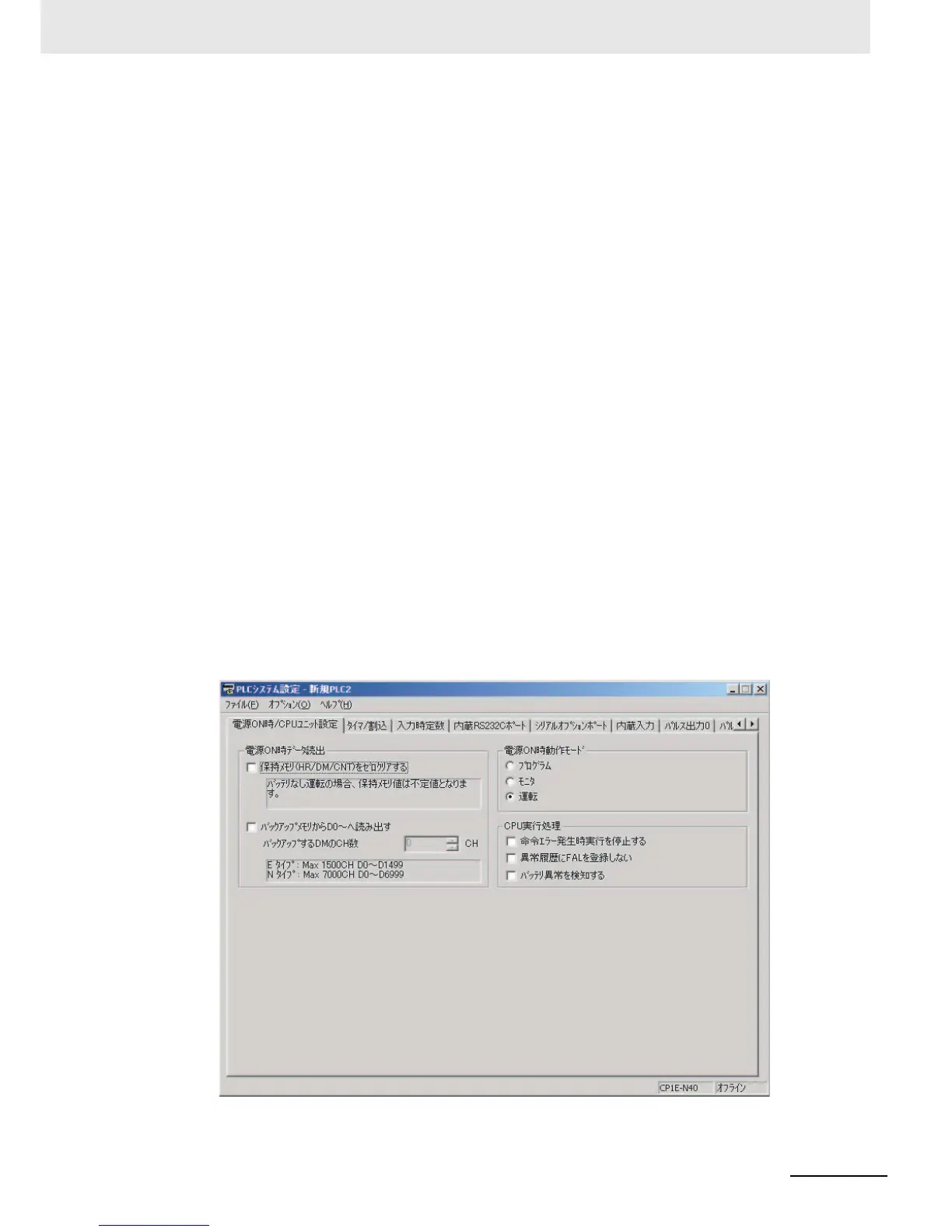
• Clearing All Bits in Held Areas at Startup
Select the Clear Held Memory (HR/DM/CNT) to Zero Check Box in the Startup Data Read Area in
the PLC Setup.
Note Only the specified words in the DM Area will be read from the backup EEPROM if the D0-
from backup memory Check Box is selected.

 Loading...


