Appendices
A-34
CP1E CPU Unit Hardware User’s Manual(W479)
Note The hood (FG) is internally connected to the ground terminal (GR) on the CPU Unit.
Therefore, the FG is grounded by grounding the power supply ground terminal (GR). Although there is con-
ductivity between the hood (FG) and pin 1 (FG), connect the shield to both the hood and pin 1 to reduce the
contact resistance between the shield and FG and thus provide better noise resistance.
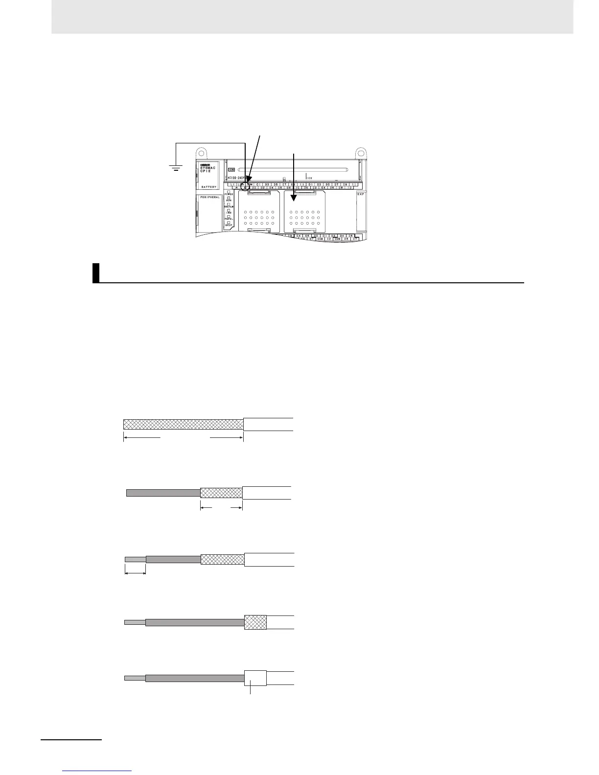
Use the following steps to wire connectors.
See the following diagrams for the length of the cable portion to be cut in each step.
z Shield Connected to Hood (FG)
1
Cut the cable to the required length.
2
Remove the specified length of the sheath from the cable using a knife.
Be careful not to scratch the braided shield.
3
Trim off the braided shield using scissors.
4
Remove the insulation from each conductor using a stripper.
5
Fold back the braided shield.
6
Wrap aluminum foil tape around the folded shield.
Wiring Connectors
RS-232C Option Board
Ground to
100Ω or less
Power supply ground terminal
25mm (RS-422A)
40mm(RS-232C)
10mm
5mm
Aluminum foil tape

 Loading...


