A-35
Appendices
CP1E CPU Unit Hardware User’s Manual(W479)
A-4 Wiring for Serial
Communications
App
A-4-1 Recommended RS-232C Wiring
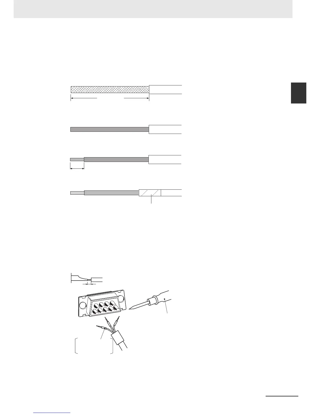
z Shield Not Connected to Hood (FG)
1
Cut the cable to the required length.
2
Remove the specified length of the sheath from the cable using a knife.
Be careful not to scratch the braided shield.
3
Trim off all the braided shield using scissors.
4
Remove the insulation from each conductor using a stripper.
5
Wrap adhesive tape around the conductor from which the braided shield was removed.
z Soldering
1
Place a heat-shrinking tube on each conductor.
2
Temporarily solder each conductor to the corresponding connector terminals.
3
Completely solder each conductor.
25mm (RS-422A)
40mm(RS-232C)
5mm
Adhesive tape
Soldering iron
Heat-shrinking tube
Inside diameter:
1.5 mm, l = 10
1 mm

 Loading...


