109
Pulse I/O Board Section 2-2
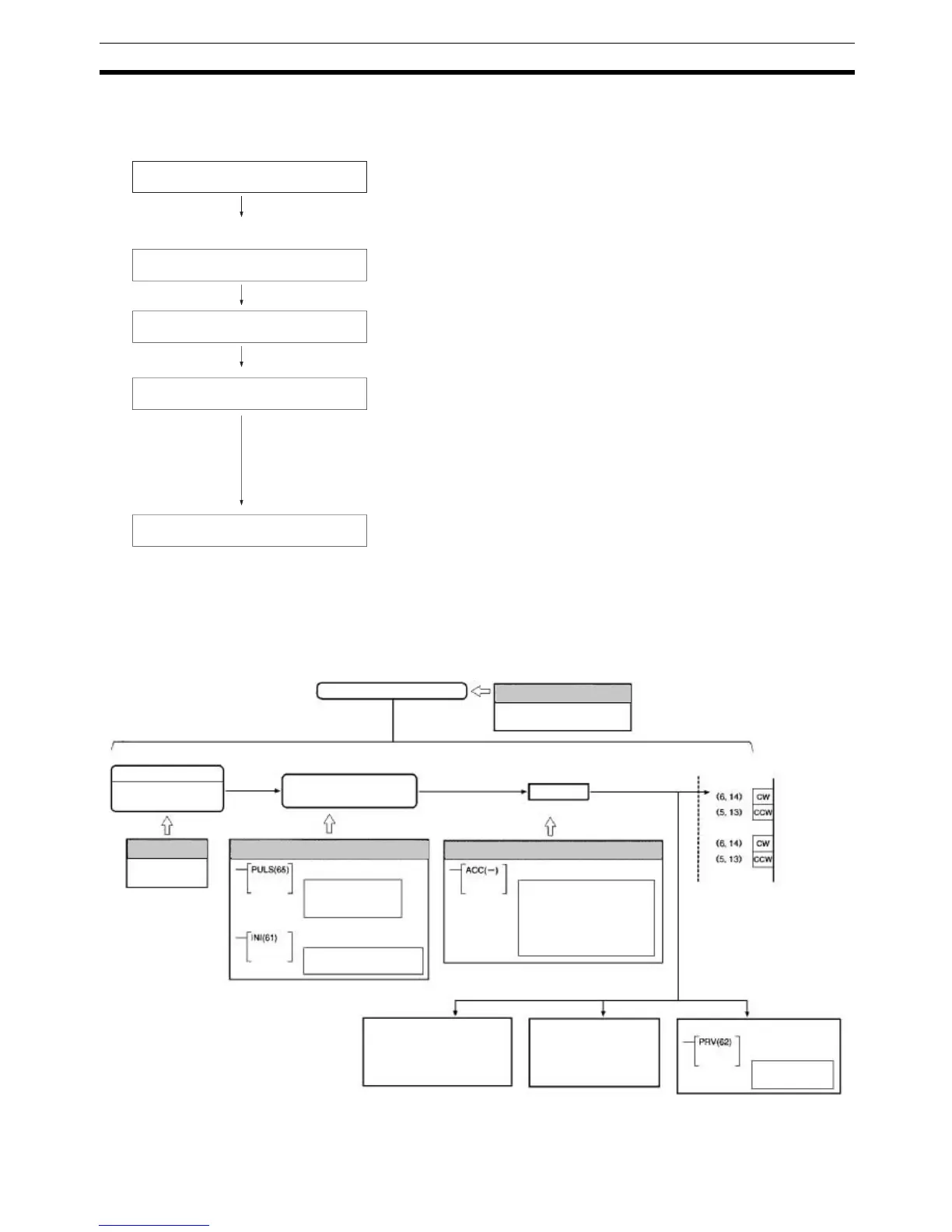
Trapezoidal Pulse Output
With Different
Acceleration/Deceleration
The following flowchart shows the procedure for using PULS(65) and
ACC(––) to perform trapezoidal pulse outputs with different acceleration/
deceleration rates.
Determine port mode.
Determine pulse output port.
Mount Board and wire output.
PC Setup
(DM 6611/DM 6643/DM 6644)
Ladder Program
Simple Positioning Mode:
All functions of ACC(−−) can be used.
High-speed Counter Mode:
Modes 1 to 3 of ACC(−−) can be used; Mode 0 (Acceleration + Indepen-
dent) is disabled.
Port 1 or port 2.
Output:
CW/CCW with/without 1.6 kΩ resistance.
Power supply for output: 5/24 V DC
Port Mode Setting (DM 6611):
Set to High-speed Counter Mode (0000 Hex) or Simple Positioning Mode
(0001 Hex). See note.
Operation settings for ports 1 and 2 (DM 6643/DM 6644):
Set to fixed duty factor.
Note: ACC(−−) Mode 0 (Acceleration + Independent) cannot be used in
High-speed Counter Mode.
SET PULSES, PULS(65):
Set number of output pulses for each port.
ACCELERATION CONTROL, ACC(−−):
Port-specific trapezoidal acceleration/deceleration pulse output control with
different acceleration/deceleration rates.
MODE CONTROL, INI(61):
Stop pulse output to a specified port.
HIGH-SPEED COUNTER PV READ, PRV(62):
Read pulse output status of a specified port.
Fixed duty factor pulse output
Trapezoidal Acceleration/
Deceleration Pulse Outputs
ACCELERATION CONTROL
No. of pulses output
8-digit BCD (00000001
to 16777215)
MODE CONTROL
Mode setting
Target: 0 to 50 kHz
Acc/dece rate (separate):
4.08 ms
10 Hz to 2 kHz
Starting pulse output
Each cycle
Each execution
Pulse output status
AR 05 to AR 06
Pulse output PV
Port 1: IR 237, IR 236
Port 2: IR 239, IR238
HIGH-SPEED
COUNTER PV
READ
Output status
read
Pulse I/O Board
− Pulse output
− Port 1 (CN1)
− Pulse output
− Port 2 (CN2)
Port Mode Setting
Simple Positioning or
High-speed Counter Mode
Pulse output stop
Pulse output PV change
Output
Each cycle
Trapezoidal Acceleration/Deceleration Pulse Outputs
PC Setup
Bits 12 to 15 of
DM 6643/DM 6644 set to 0.
Ladder Program
OUTPUT PULSES
Ladder Program
PC Setup
Set DM 6611 to
0001.