110
Pulse I/O Board Section 2-2
PC Setup Settings Before outputting pulses from port 1 or 2, switch the PC to PROGRAM mode
and enter the following settings in the PC Setup.
Port Mode Setting (DM 6611)
The instructions that can be used are limited by the Port Mode setting for
ports 1 and 2 of the Pulse I/O Board. The Port Mode is specified in the PC
Setup (DM 6611).
Port Mode Setting and
Instructions
The following tables show the port mode settings and the instructions that can
be used with various pulse outputs.
Pulse Output without Trapezoidal Acceleration/Deceleration
All instructions can be used regardless of the port mode setting.
Pulse Output with Trapezoidal Acceleration/Deceleration and the Same
Acceleration/Deceleration Rate
PLS2(––) (PULSE OUTPUT) cannot be used in High-speed Counter Mode. It
is not possible to perform trapezoidal acceleration/deceleration pulse output
using the same acceleration/deceleration rates.
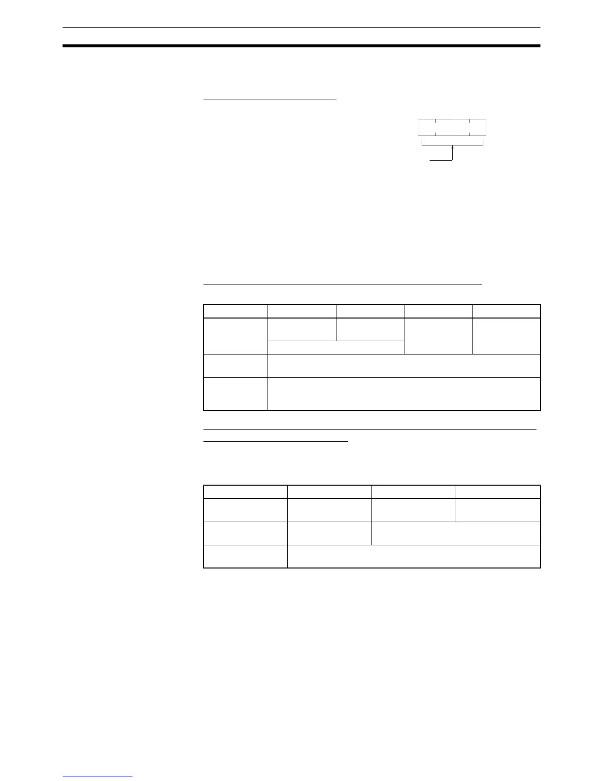
15 0
DM 6611
Bit
Port Mode Setting for Pulse I/O Board
0000 Hex: High-speed Counter Mode
0001 Hex: Pulse Output Mode
Default: 0000 (High-speed Counter Mode)
Instruction PULS(65) SPED(64) INI(61) PRV(62)
Function Sets number of
pulses
Sets frequency Stops pulse
output
Reads pulse
output status
(Used in combination.)
High-speed
Counter Mode
Enabled
Simple
Positioning
Mode
Enabled
Instruction PLS2(––) INI(61) PRV(62)
Function Sets number of
pulses
Stops pulse output Reads pulse output
status
High-speed
Counter Mode
Disabled Enabled
Simple Positioning
Mode
Enabled