102
Variable Area Map Section 5-10
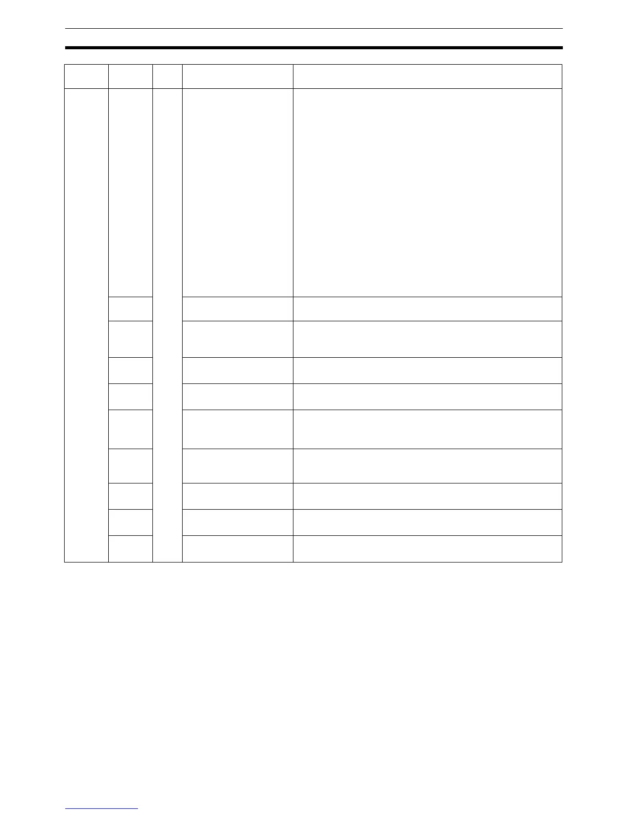
C3 0110 - Auxiliary output 1 alloca-
tion
00000000H (0): Heating control output for ch1
00000001H (1): Cooling control output for heating/cooling con-
trol for ch1
00000002H (2): Alarm 1 and HB alarm OR output for ch1
(See note 1.)
Alarm 1 and sensor error alarm OR output for
ch1(See note 2.)
00000003H (3): Alarm 2 output for ch1
00000004H (4): Alarm 3 output for ch1
00000005H (5): Heating control output for ch2
00000006H (6): Cooling control output for heating/cooling con-
trol for ch2
00000007H (7): Alarm 1 and HB alarm OR output for ch2 (See
note 1.)
Alarm 1 and sensor error alarm OR output for
ch2 (See note 2.)
00000008H (8): Alarm 2 output for ch2
00000009H (9): Alarm 3 output for ch2
0111 Auxiliary output 2 alloca-
tion
Same as for auxiliary output 1 allocation
0112 Operation after power
ON
00000000H (0): Stop
00000001H (1): Continue (Continues the operation status from
before the power supply was stopped.)
0113 Communications data
length
00000007H (7): 7
00000008H (8): 8
0114 Communications stop bit 00000001H (1): 1
00000002H (2): 2
0115 Communications parity 00000000H (0): None
00000001H (1): Even
00000002H (2): Odd
0116 Communications
response transmission
wait time
00000000H to 0000270FH (0 to 9,999)
0117 No. of multi-SP uses 00000000H (0): No multi-SP
00000001H (1): Switch between SP0/1
0118 Event input allocation 00000000H (0): None
00000001H (1): RUN/STOP
0119 Use multi-SP 00000000H (0): OFF
00000001H (1): ON
Variable
type
Address ch Setting data name Description