Controlling/Outputting in Parallel
110
FQ-CR2 User’s Manual
Turning the ERROR Signal OFF
The ERROR signal turns ON when an error occurs.
After removing the cause of the error, turn the ERROR signal OFF using one of the following methods.
Method 1: Input an error clear command from an external device such as a PLC.
Method 2: Input a measurement trigger again.
(For example, turn the TRIG signal ON during a one-shot measurement.)
The ERROR signal will turn OFF when measurement is executed correctly.
Settings
[In/Out] − [I/O setting] − [I/O terminals] − [Input] − [Input mode]
Press [Expand mode].
Wiring
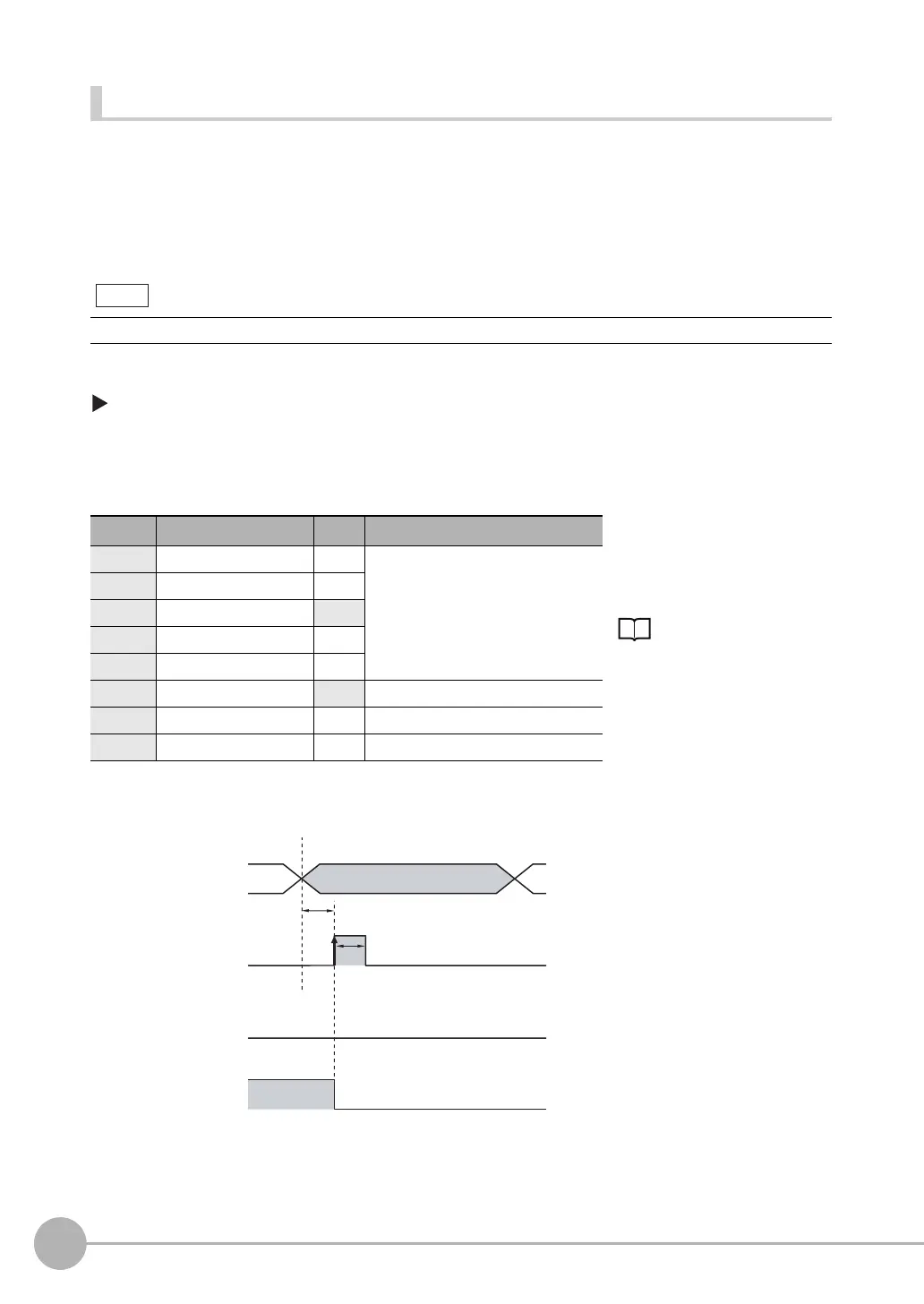
Timing Chart
This function can be used in Run Mode only.
Color Signal State Description
The signals shown at the left
are used.
Refer to the following
information for signal wiring.
2-4 Wiring: p. 26
Gray IN0 OFF Command parameter for clearing errors
Green IN1 OFF
Red IN2 ON
White IN3 OFF
Purple IN4 OFF
Ye l l o w IN5 ON Command input for clearing errors
Orange OUT1 (BUSY) -- Processing in progress (default)
Light blue OUT2 (ERROR) -- ERROR signal (default)
1 Turn OFF IN0 to IN1 and IN3 to IN4
and turn ON IN2.
2 Turn ON the IN5 signal while the
BUSY signal is OFF to clear the error.
Note
OFF
ON
OFF
ON
OFF
ON
ERROR signal
BUSY signal
IN5 signal ON for 1 ms min.
Allow 5 ms min. and then
turn ON IN5.
IN0 to IN4 signals
FQ Sensor User Manual.book 110 ページ 2011年7月8日 金曜日 午後2時30分
 Loading...

